Home » ISX11.9 CM2250 - Service Manual » Cummins ISX11.9 CM2250 – Service Manual 001-012   Camshaft Gear (Camshaft Installed)

Cummins ISX11.9 CM2250 – Service Manual 001-012   Camshaft Gear (Camshaft Installed)

Preparatory Steps

TOC

 WARNING 

Batteries can emit explosive gases. To reduce the possibility of personal injury, always ventilate the compartment before servicing the batteries. To reduce the possibility of arcing, remove the negative (-) battery cable first and attach the negative (-) battery cable last.
 WARNING 

Do not remove the pressure cap from a hot engine. Wait until the coolant temperature is below 50°C [120°F] before removing the pressure cap. Heated coolant spray or steam can cause personal injury.
 WARNING 

Coolant is toxic. Keep away from children and pets. If not reused, dispose of in accordance with local environmental regulations.

SMALL | MEDIUM | LARGE

Remove

TOC

Camshaft Gear Removal Tool Kit, Part Number 4919610
Item
Part Number
Description
Quantity
1
137795
Screw, Hexagon Head Cap
1
2
4919106
Cylinder, Hydraulic
1
3
4919105
Eye, Lifting
1
4
4919747
Plate, Remover
1
5
4919748
Jaw, Replacer
2
6
4919750
Adapter
1
7
3093948
Nut, Regular Hexagon
2

SMALL | MEDIUM | LARGE


 WARNING 

The puller assembly is heavy. Use a lifting device when securing it to the cam gear.
 WARNING 

The cam gear and puller assembly may fall when released and cause serious personal injury.

Use the front camshaft gear removal tool kit, Part Number 4919610, to remove the gear from the camshaft.

Assemble the lifting eye (1) to the gear puller plate (2) using the included capscrew.

Attach a lift device to the lifting bracket on the gear puller.

SMALL | MEDIUM | LARGE


Install the remover jaws (1) into the two round holes in the gear.

SMALL | MEDIUM | LARGE


Place the puller assembly over the remover jaws.

Hand tighten the nuts to secure the assembly to the gear.

Thread the hydraulic cylinder into the assembly until the threads bottom out.

SMALL | MEDIUM | LARGE


 WARNING 

Keep hands clear of the cam gear and puller during removal. Failure to keep clear may result in personal injury.

Connect the appropriate air/hydraulic pump hose to the gear puller hydraulic cylinder.

Connect the other end of the hydraulic pump hose to the output side of the air/hydraulic pump, Part Number 3823622.

Connect the air hose to the input side of the air/hydraulic pump.

SMALL | MEDIUM | LARGE


Make sure that the lifting device is attached to the gear puller lifting bracket.

Step away from the engine to avoid personal injury when the camshaft gear and puller are released from the camshaft.

Slowly depress the air/hydraulic pump pedal on the side labeled “PRESS” and hold until the camshaft gear and puller are released from the camshaft.

SMALL | MEDIUM | LARGE


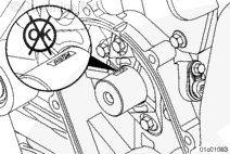
After the camshaft gear and puller have been removed from the camshaft, depress the air/hydraulic pump pedal on the side labeled “RELEASE” and hold until the pressure is released.

Remove the camshaft gear from the puller.

SMALL | MEDIUM | LARGE


Disconnect the air hose from the input side of the air/hydraulic pump.

Disconnect the air/hydraulic pump hose from the gear puller hydraulic cylinder.

Disconnect the other end of the hydraulic pump hose from the output side of the air/hydraulic pump.

Remove the lifting device from the puller lifting bracket.

SMALL | MEDIUM | LARGE
   

Disassemble

TOC

Remove the four capscrews and camshaft position sensor plate from the rear of the camshaft gear.

SMALL | MEDIUM | LARGE
   

Inspect for Reuse

TOC

Inspect the camshaft gear for cracks and chipped or broken teeth.

Inspect the bore of the gear for frets or burrs.

Remove any burrs with a fine grade abrasive pad, such as Scotch-Brite™ 7448, Part Number 3823258, a fine honing stone, or equivalent.

If the frets, burrs, or raised material can not be removed, replace the gear.

SMALL | MEDIUM | LARGE


Inspect the camshaft gear keyway for burrs.

Remove burrs with a fine grade abrasive pad such as Scotch-Brite™ 7448, Part Number 3823258, a fine honing stone, or equivalent.

If the keyway is damaged or the burrs can not be removed, the camshaft gear must be replaced.

SMALL | MEDIUM | LARGE


Inspect the camshaft nose for frets or burrs.

Remove any burrs with a fine grade abrasive pad such as Scotch-Brite™ 7448, Part Number 3823258, a fine honing stone, or equivalent.

If frets or burrs can not be removed, replace the camshaft.

Inspect the thrust surface of the camshaft for grooves or heavy wear.

SMALL | MEDIUM | LARGE


Inspect the camshaft position sensor plate for cracks or other damage.

Replace the camshaft position sensor plate if it is cracked or otherwise damaged.

SMALL | MEDIUM | LARGE
   

Assemble

TOC

NOTE: The camshaft position sensor plate is not symmetric and can only be oriented in one position.

Align and assemble the camshaft position sensor plate to the rear face of the camshaft gear.

Tighten the four capscrews.

Torque Value:  10  n.m  [89 in-lb]

SMALL | MEDIUM | LARGE
   

Install

TOC

If removed, install the camshaft thrust bearing prior to installing the key.  Refer to Procedure 001-056 in Section 1.

SMALL | MEDIUM | LARGE


Remove the camshaft rear cover plate. Refer to Procedure 001-011 in Section 1.

Install three ½ inch UNC capscrews into the 3-bolt pattern shown. This will secure the camshaft in position while installing the front camshaft gear.

SMALL | MEDIUM | LARGE


NOTE: Gear housing clearance makes key installation more difficult. Use care in seating the key.

Be sure the gear mounting surface is clean and free of oil, dirt, or debris.

Use a leather hammer to install the camshaft gear key.

SMALL | MEDIUM | LARGE


Heat the gear in an oven for a minimum of 2 hours, but not longer than 4 hours.

Measurements
  celsius fahrenheit
Oven Temperature 255 490

SMALL | MEDIUM | LARGE


 WARNING 

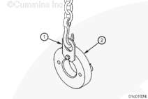
Use insulated gloves, Part Number 3823730, and/or hot clamp pliers, Part Number 3823732, when handling heated parts. Hot parts can cause serious personal injury.
 CAUTION 

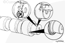
The timing marks and gear part number must be facing away from the camshaft when the gear is installed to prevent engine damage.

Use Lubriplate™ 105, or equivalent, to coat the camshaft nose before installing the camshaft gear.

Remove the gear from the oven. Install the gear on the camshaft within 30 seconds after removing it from the oven.

Align the gear keyway with the key in the camshaft and install the gear on the camshaft until the camshaft contacts the positive stop on the gear.

SMALL | MEDIUM | LARGE


Install a C-clamp around the gear housing and the camshaft gear to hold the gear in position as it cools.

Remove the C-clamp after the gear has cooled for at least 10 minutes.

SMALL | MEDIUM | LARGE


Measure the camshaft end clearance. Refer to Procedure 001-065 in Section 1.

SMALL | MEDIUM | LARGE


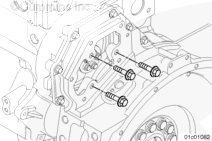
Remove the three ½ inch UNC capscrews from the flywheel housing that were used to secure the camshaft in position while installing the front camshaft gear.

SMALL | MEDIUM | LARGE
   

Finishing Steps

TOC

 WARNING 

Batteries can emit explosive gases. To reduce the possibility of personal injury, always ventilate the compartment before servicing the batteries. To reduce the possibility of arcing, remove the negative (-) battery cable first and attach the negative (-) battery cable last.
 WARNING 

Coolant is toxic. Keep away from children and pets. If not reused, dispose of in accordance with local environmental regulations.

SMALL | MEDIUM | LARGE
Last Modified:  03-Aug-2010