There is a timing dowel pin on the rear face of the crankshaft that aligns the flywheel. If the dowel pin is damaged, broken, or missing, this can cause improper engine performance. The face runout can also be out of specification.
Check to see if the dowel pin is installed in the crankshaft.
Inspect the dowel pin for damage.
If the dowel pin is damaged or broken, replace the dowel pin.
The flywheel mounting capscrews must be a minimum of SAE Grade 8 with rolled threads. Use identical capscrews as replacements to avoid possible flywheel malfunction, resulting in personal injury or property damage.
Lubricate the threads and underneath the heads of the capscrews with clean 15W-40 oil.
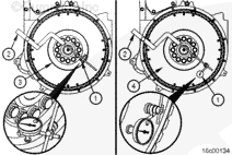
Use dial indicator gauge (1), Part Number 3376050, or equivalent, and dial gauge attachment (2), Part Number ST-1325, to inspect the flywheel bore (3) and face (4) runout.
Install the attachment to the flywheel housing.
Install the gauge on the attachment.
Install the contact tip of the indicator against the inside diameter of the flywheel bore, and set the dial indicator at zero.
There is a timing dowel pin on the rear face of the crankshaft that aligns the flywheel. If the dowel pin is damaged, broken, or omitted, improper engine performance and/or face runout will be out of specfication.
Check to see if the dowel pin in the crankshaft is installed.
Inspect the dowel pin for damage. If the dowel pin is damaged or broken, replace the dowel pin.
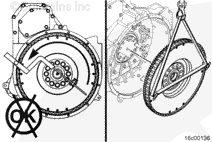
Install the contact tip of the indicator against the flywheel face as close to the outside diameter as possible to inspect the face runout.
When locating the contact tip, see the Flywheel Face Runout Total Indicator Reading Table later in this procedure. Locate the contact tip so that it corresponds with a radius listed in the table, but is still as close to the outside diameter of the flywheel as possible, to inspect the flywheel face (1) runout.
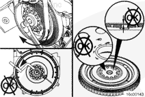
Push the flywheel forward to remove the crankshaft end clearance.
Adjust the dial on the indicator until the needle points to zero.
Rotate the crankshaft one complete revolution. Measure and record the flywheel runout at four equal points on the flywheel. Refer to Procedure 009-035 in Section 9.
The flywheel must be pushed toward the front of the engine to remove the crankshaft end clearance each time a point is measured.
Determine the total indicator reading (TIR).
TIR is determined by calculating the difference between the highest and lowest measurement from the four locations measured.
 CAUTION

 WARNING


;)
;)
;)
;)
;)
;)
;)
;)
;)
;)
;)
;)
;)
;)
;)
;)
;)
;)
;)
;)
;)
;)
;)
;)
;)
;)
;)
;)
;)
;)