
Installation sequence
Follow the removal sequence in reverse.
• After installation, measure and adjust the boost pressure. (See “ON-VEHICLE INSPECTION AND ADJUSTMENT”.)

Installation procedure
•Installation: Turbocharger
Before installing the turbocharger assembly, pour engine oil into the oil hole to ensure smooth operation of the internal parts.

Installation: Air inlet hose
• Fit the air inlet hose over the air outlet fitting as deep as its end touches the buildup on the fitting.


NOTE
• Do not remove the joint and position bolt from the turbocharger actuator and turbine assembly unless they are defective.
Installation sequence
Follow the removal sequence in reverse.

Work before removal
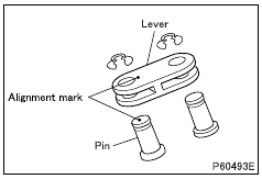
Alignment mark
• Put alignment marks on the pin and lever.
Work after disassembly
Cleaning
• Before cleaning, visually check the disassembled parts for scorches, abrasion and other marks that may be difficult to see after cleaning. Replace any part that appears defective.
• Immerse the disassembled parts in a non-flammable solvent (a 5 to 10 aqueous solution of Oil Clean from New Hope Co., Ltd.).
Take out the parts and blow them dry with compressed air. Remove any hard deposits with a stiff brush or plastic scraper.
• Again, immerse the parts in the solvent.
• Blow them dry using compressed air.

Inspection procedure
Inspection: Turbine assembly
(1) Visual check
• Replace the turbocharger if the compressor cover is damaged or if smooth rotation is not ensured.
(2) Play in shaft axial direction
• Install the turbine assembly on a flat board with its flanged section pressed against the board. Then, measure the runout using a dial gauge.
• If the measurement exceeds the limit, replace the turbine assembly.

•Inspection: Pin outer diameter
If the measurement is less than the limit, replace the pin.

•Inspection: Lever inner diameter
If the measurement exceeds the limit, replace the lever.

•Inspection: Joint inner diameter
If the measurement exceeds the limit, replace the joint.
Inspection: Turbocharger actuator shaft stroke
• Conduct the turbocharger actuator check with the turbocharger electronic drive unit mounted on the vehicle.
• Mark the turbocharger actuator shaft at the zero stroke point.
• Select [A5: VGT] from [Actuator Test] on the Multi-Use Tester screen and execute it. The turbocharger actuator shaft will be brought into a full stroke state.
• Measure the amount of stroke from the full stroke point to the marked point.
• If the measurement is out of specified standard value, replace the turbocharger actuator.

Installation procedure
Installation: Position bolt
• Move the control crank to the maximum position, and install the position bolt to the turbine assembly.
Make sure that the position bolt is in contact with the control crank.
• In this state, give the position bolt two and half turns, then tighten the lock nut to secure the position bolt.

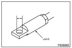
Installation: Joint
• With the actuator shaft in a zero stroke state, adjust the distance between the end faces of the actuator and joint to the illustrated value.
Adjusting guide: 1 mm with one full turn of joint
• After the adjustment, tighten the lock nut.

Installation: Pin
• Install the pins in the lever according to alignment marks.
