Pin Grip Inspection
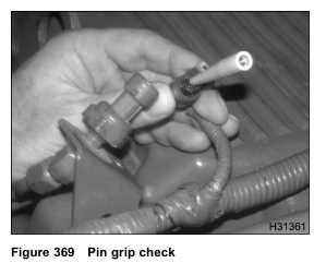
1. Disconnect the harness connector from the sensor or actuator.
2. Inspect for corrosion, bent pins, spread pins, or conditions that could cause a loose or intermittent connection.
3. Check the pin grip in the female pin by inserting the correct tool from Terminal Test Adapter Kit.
Operational Diagnostics
Operational Diagnostic tests use the MasterDiagnostics® Continuous Monitor Test.
For help, see “Diagnostic Software Operation” in Section 3 (page 68) for procedure to run the Continuous Monitor Test.
VREF Tests using MasterDiagnostics®
1. Plug the Electronic Service Tool (EST) tool into the American Trucking Association (ATA) datalink connector and start MasterDiagnostics®.
2. Disconnect sensor to be tested.
3. Connect breakout harness to harness only.
4. Turn the ignition switch to ON.
5. Monitor signal voltage with the EST using continuous monitor session and initiating KOEO Continuous Monitor Test. Voltage should be near 0, unless the signal circuit is shorted or incorrectly wired to VREF, B+, or other voltage sources. See Circuit Diagnostics in this section for sensor specifications.
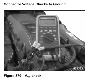
6. Use a Digital Multimeter (DMM) to verify VREF at BLUE pin (VREF) in breakout harness (voltage should be 5 V ± 0.5 V). Connect positive to BLUE and negative to chassis ground. If voltage is greater than 5.5 V, check VREF for short to B+. If voltage is less than 4.5 V, check VREF for open or short to ground.
7. Install 500 ohm harness between GREEN (signal circuit), and BLUE (VREF) pin of breakout harness.
Monitor signal voltage with EST.
If voltage is less than 4.5 V, check signal circuit for open or short to ground.
8. Use a DMM to check resistance from BLACK pin (signal ground) of breakout harness to chassis ground.
If resistance is greater 5 ohm, check for open or high resistance between ECM and sensor connector.
9. Connect engine or chassis harness to sensor.
10. Use the EST to clear DTCs. If an active DTC remains after checking test conditions, replace sensor.
Temperature Sensor Tests using MasterDiagnostics®
1. Plug the Electronic Service Tool (EST) tool into the ATA connector and start MasterDiagnostics®.
2. Disconnect sensor to be tested.
3. Connect breakout harness to harness only.
4. Turn the ignition switch to ON.
5. Monitor signal voltage with the EST using continuous monitor session and initiating KOEO Continuous Monitor Test (voltage should be greater than 4.6 V). See Circuit Diagnostics in this section for sensor specifications.
If voltage is less than 4.6 V, check signal circuit for short to ground.
If voltage is greater than 5.5 V, check signal circuit for short to B+.
6. Install 3–Banana plug harness between GREEN (signal circuit), and BLACK (signal ground) pin of breakout harness.
If voltage is more than 0.127 V, check ground circuit for open or high resistance. See Circuit Diagnostics in this section for sensor specifications.
7. Remove 3–Banana plug harness.
8. Connect engine or chassis harness to sensor.
9. Use the EST to clear DTCs.
If an active DTC remains after checking test conditions, replace sensor.
Pin-Point Diagnostics
Some Pin-Point Diagnostic tests use the MasterDiagnostics® Output State Tests.
For help, see “Diagnostic Software Operation” in Section 3 (page 68) for procedure to run the Low and High
Output State Tests.
Procedure
1. Turn the ignition switch to ON.
2. Connect breakout harness to the harness only.
3. Measure voltage at each pin with a DMM.
4. Compare sensor or actuator voltage readings with the expected voltages. See Circuit Diagnostics in
this section for circuit specifications. If a breakout harness is not available, use the correct tool from Terminal Test Adapter Kit. Do not directly probe the connector pins with the DMM leads. For a circuit with an expected voltage, this test will verify circuit integrity.
5. Turn the ignition to OFF.
For circuits without an expected voltage, this test will determine if that circuit is shorted or incorrectly wired
to ground, VREF, B+ or other voltage sources.
Procedure
NOTE: The truck Chassis Electrical Circuit Diagram Manual should always be used for chassis ground
circuit information.
1. Disconnect chassis connector 9260.
NOTE: Connector 9260 is a 2-wire connector usually located in the battery box. Pin A is the chassis ground connection for the ECM and IDM.
See truck Chassis Electrical Circuit Diagram Manual for complete chassis side ECM and IDM ground circuit information.
2. Connect breakout harness to harness only.
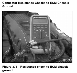
3. Use breakout harness to measure resistance from the lead of the breakout harness to the connector 9260 Pin A.
See Circuit Diagnostics in this section for circuit specifications.
Sensor signal ground circuits should measure less than 5 ohms.
VREF and signal circuits should measure more than 1 k ohm.
The control side of an actuator will measure more than 1 k ohms, but the expected voltage for the other side of the actuator circuit will measure the voltage that the control side was switching, either power or ground.
If the ECM is switching the ground circuit, the other side of the actuator circuit should measure more than 1 k ohms from the connector pin to connector 9260 Pin A.
If the ECM is switching the power circuit, the other side of the actuator circuit should measure less than 5 ohms from the connector pin to connector 9260 Pin A.
Procedure
NOTE: The truck Chassis Electrical Circuit Diagram Manual should always be used for chassis ground
circuit information.
1. Disconnect chassis connector 9260.
NOTE: Connector 9260 is a 2-wire connector usually located in the battery box. Pin A is the chassis ground connection for the ECM and IDM. See truck Chassis Electrical Circuit Diagram Manual for complete chassis side ECM and IDM ground circuit information.
2. Connect breakout harness to harness only.
3. Disconnect negative battery cable.
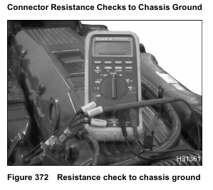
4. Use breakout harness to measure resistance from the lead of the breakout harness to the negative battery cable.
See Circuit Diagnostics in this section for circuit specifications. Sensor signal ground circuits should measure greater than 500 ohms. VREF and signal circuits should measure more than 1 k ohm.
The control side of an actuator will measure more than 1 k ohms, but the expected voltage for the other side of the actuator circuit will measure the voltage that the control side was switching, either power or ground.
If the ECM is switching the ground circuit, the other side of the actuator circuit should measure more than 1 k ohms from the connector pin to battery ground.
If the ECM is switching the power circuit, the other side of the actuator circuit should measure greater than 500 ohms from the connector pin to battery ground.
Harness Resistance Checks
Procedure
CAUTION: To avoid engine damage, turn the ignition switch to OFF before disconnecting the connector or
relay for the ECM and IDM. Failure to turn the switch to OFF will cause a voltage spike and damage to electrical components.
1. Check harness resistance if high resistance or an open circuit is suspected.
2. Connect breakout harness to harness only.
3. Connect breakout box to the ECM end of the harness only.
4. Measure resistance from breakout box pin to the breakout harness pin. Circuit wires should have a
resistance of less than 5 ohms.
See Circuit Diagnostics in this section for circuit specifications.
Operational Voltage Checks
Operational voltages checks determine In-range faults or intermittent connections.
To determine in-range faults and intermittent connections, monitor a suspected circuit and recreate conditions likely to cause the problem.
Monitor signal voltage with the EST using continuous monitor session and initiating KOEO Continuous Monitor Test. See Circuit Diagnostics in this section for circuit specifications.
Use a DMM and breakout harness or a DMM and breakout box. See Circuit Diagnostics in this section for circuit specifications.