The illustration shows the fuel pressure sensor on the fuel rail of the of the 2.0L Duratorq-TDCi (DW) diesel engine.
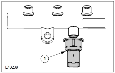
1 Fuel pressure sensor
NOTE: The fuel pressure sensor must on no account be removed from the fuel rail during servicing.
The fuel pressure sensor measures the current fuel pressure in the fuel rail very accurately and quickly and delivers a voltage signal to the PCM in accordance with the current pressure level.
The fuel pressure sensor operates together with the fuel metering valve and the fuel pressure control valve on the high pressure pump in a closed control loop.
The fuel pressure sensor signal is used to:
• determine the injected fuel quantity,
• determine the start of injection,
• actuate the fuel metering valve on the high pressure pump and the fuel pressure control valve.
Effects of faults
In the case of a fault, the PCM switches from closed loop to open loop control and performs a calculation using an average value (approx. 350 bar), which is made available via a limited-operation map.
The average value used is within a safe range (in order to prevent excessive pressure). This means that the injected fuel quantity and consequently the engine power output is restricted to a specified limit from approx. 2800 rpm upwards.
Note: For a quick check of the fuel pressure sensor, disconnect the wiring harness connector while the engine is running. The engine should run more roughly.
After reconnecting the wiring harness connector, the engine should return to smooth running.
Diagnosis
The fuel pressure sensor is monitored for the following functions:
• short circuit, open circuit and open control loop (via the limit range check),
• logical rise/fall rate of the signal (loose contact detection)
• sensor-specific signal fluctuations,
• correct pressure reduction after the engine is stopped.
Monitoring of the sensor-specific signal fluctuations serves to check whether the signal emitted by the sensor is subject to “normal fluctuations”.
A pre-condition for this check is that no faults are present in the sensor supply voltage and that there is no short circuit, open circuit or open control loop. Moreover, the engine must be running in the partial load range.
During monitoring, the PCM checks whether the signal fluctuations emitted by the sensor are within a calibrated minimum limit. If the fluctuations are inferior to the calibrated minimum limit, a DTC is stored.
This is in order to check whether the sensor is sticking at a certain point when emitting the signal.
Monitoring for correct pressure reduction is performed after the engine is switched off using the ignition key (ignition OFF) as well as if the engine cuts out (ignition ON or OFF).
The PCM checks for pressure reduction in the high pressure system.
When the engine is stopped, a timer is activated. The fuel pressure present at timeout is registered and compared with the calibrated limit in the PCM. If the measured value exceeds the calibrated limit, this leads to a DTC being stored.
The substitution strategy is designed so that the EOBD limits are not exceeded in the case of a fuel pressure sensor fault. Therefore, this is a non MIL active component.
In the case of a fault, the engine system fault warning lamp illuminates.
Typical fault function limits:
• Sensor voltage < 0.19 V (corresponds to approx. 0 bar)
• Sensor voltage > 4.81 V (corresponds to approx. 1800 bar)
• Voltage fluctuations during partial load operation > 0.01 V
Possible diagnostic trouble codes: P0190, P0191, P0192, P0193, P0194.