See Figure 2-33. The lubrication system of the 6.2L diesel engine is composed of:
• Oil pan reservoir
• Filter
• Pump
• Galleries

Seven quarts of oil are required for this engine. The oil pan acts as a reservoir for holding the oil waiting to be circulated through the engine. The oil pan is attached to the bottom side or pan rail of the engine.
The lubricating system of this engine is a pressure feed type which means that a pump forces oil through the galleries to the necessary parts. The pump is mounted to the bottom side of the number five main bearing cap. Extending down from the pump and into the oil is a pick-up tube with a screen cover to filter out foreign material.
Oil is picked up by this tube and pumped through the oil pump. The pump is a gear type which uses 2 meshing gears. As these gears rotate in opposite directions, the spaces between the gear teeth and the housing fill with oil
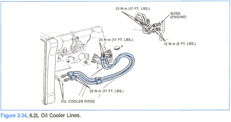
from the inlet side of the pump. Then as the teeth mesh, the oil is forced out through the outlet tube. The pump is driven from the engine camshaft by means of an intermediate shaft. The oil is next pumped through a cooler located in the radiator (Figure 2-34) which cools the oil and thus helps to remove engine heat.
From the cooler the oil passes through a filter. This filter is a cartridge type and all oil going to the engine should pass through this filter. The cartridge is made of materials that trap foreign materials to prevent it getting to engine components. The filter used in this engine is called a full flow filter, because all engine oil normally flows through it. If this full flow filter becomes clogged, the engine is equipped with a by-pass valve which is spring loaded. This valve protects the engine from oil starvation by opening when increased pump pressure tries to pump oil through a clogged filter. When the pressure causes the by-pass valve to open, the oil by-passes the filter and the engine continues to receive lubrication. Replacement of the filter periodically will prevent damage to the engine due to a clogged filter.
From the filter the oil is pumped through the drilled galleries in the crankcase to the various moving metal parts in the engine. The rear crankshaft bearing is fed by a hole drilled from the rear main bearing bore to main gallery from filter to cylinder case. Oil is pumped further through the main gallery to a drilled oil gallery which has been drilled the full length of the left side of the case. Oil from this gallery feeds the camshaft babbit bearings and another gallery which runs the full length of the right side of the case. All other engine components are provided lubrication by these 2 oil galleries. Holes are drilled from camshaft bore to provide oil for main bearings #1 through #4. Lifters on the right side receive oil from the right side main oil gallery and lifters on the left side receive oil from the left side oil gallery. The lifters contain a check ball which meters oil through the hollow push rods and to the rocket arm and valve stem in the cylinder head. After a small accumulation of oil is in the head, it begins to drain back to the crank case. As mentioned before, the first four main bearings receive oil from vertical holes drilled from the cam bores to crank bores. This oil flows onto the crankshaft main bearings and provides lubrication for the crankshaft to rotate freely in its bearings. This oil also flows around the groove in each bearing to holes drilled in the crankshaft to the crankpin journals to provide lubrication there, to allow the crankpins to rotate freely in the connecting rod bearings. As the crankshaft rotates, it slings oil off the crankpins to cover cylinder walls, pistons, piston pin and piston rings. Oil drains off these parts and back to the engine.
There is also one other by-pass valve which has not yet been discussed. This is the oil cooler by-pass valve. It works much the same as the oil filter by-pass valve and opens to allow an alternate route for the oil if the cooler should become clogged.
There is an oil pressure switch which is assembled to the top rear of the cylinder case to sense oil pressure in the oil cavity.
OIL PRESSURE
Hot idle 10 PSI
Max. Cold Start 80 PSI
Average Pressure at stable
Conditions 40-45 PSI @ 2000 RPM