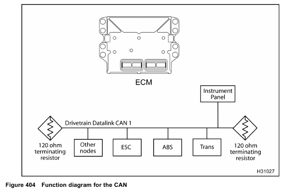
The function diagram for the CAN includes the following:
• Electronic Control Module (ECM)
• Drivetrain Datalink (CAN 1)
• Terminating resistors – 120 ohm
• Instrument panel (lamps)
Function
The Drivetrain Datalink is a Society of Automotive Engineers (SAE) term referring to one of the datalinks
common to all trucks. The Drivetrain Datalink is the communication link for the engine Electronic Control Module (ECM), cab and chassis Electronic System Controller (ESC), and the instrument panel.
The Drivetrain Datalink is also used for power train communication and control.
The ECM transmits component information across the Drivetrain Datalink to the instrument panel.
The following instrument panel components are in constant communication with the Drivetrain Datalink:
• Oil pressure gauge
• Engine oil temperature gauge
• Tachometer
• Speedometer
• Odometer / hourmeter
• Coolant temperature gauge
• Coolant level lamp
• ENGINE lamp (red)
• ENGINE lamp (amber)
• Fuel filter lamp
• Change oil message
• Cruise / PTO control
• WAIT TO START lamp
The ECM and ESC use the Drivetrain Datalink to provide the instrument panel with status information on the following features.
• Cruise control ON/OFF
• Cruise control Set / Cruise
• Cruise control resume / accelerate
• Driveline Disengagement Switch (DDS)
• Brake pedal
• AC demand
• Self-test input
• Remote Accelerator Pedal (RPS)
• In-Cab PTO / Throttle switch
Fault Detection / Management
There are no engine DTCs for CAN 1 communications.
See truck Electrical System Troubleshooting Guide.
Tools
• EST with MasterDiagnostics® software
• EZ-Tech® interface cable
• Digital Multimeter (DMM)
