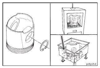
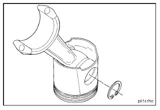
Install a new snap ring in one of the snap ring grooves of the piston pin bore on each piston.
Heat the pistons in boiling water for 15 minutes or in an oven for 30 minutes at 100° C [212° F].
Use clean 15W-40 oil to lubricate the connecting rod piston pin bore and the piston pin.
Remove the piston from the water or the oven.
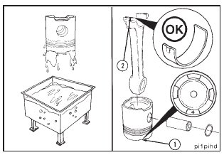
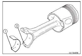
Align the pin bore of the rod with the pin bore of the piston, and install the piston pin. Do not use a hammer to install the piston pin. The piston will be damaged.
NOTE: The cylinder number of the piston top (1) must be toward the bearing tang (2) side of the rod.
Install a new snap ring in the second piston pin bore snap ring groove. The snap ring must be seated completely in the snap ring groove.
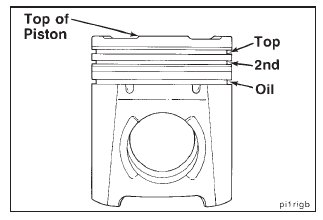
The piston ring shipping package identifies the location of each piston ring by the part number. Install the rings in the sequence shown and in the proper orientation. The first and second rings have the word ‘‘TOP’’ stamped on the ring side facing the piston crown. The oil ring is not marked.
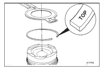
NOTE: The oil control ring is symmetrical and can be installed in either orientation.
Use piston ring expander, Part No. 3823871, to install thepiston rings with the part number, mark, or the word ‘‘TOP’’ toward the top of the piston.
NOTE: The oil control ring is symmetrical and can be installed in either orientation.
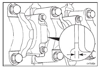
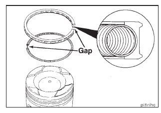
A cross-sectioned view of an oil control ring is shown. The two-piece oil control ring must be installed with the expander ring gap 180 degrees from the gap of the oil ring.
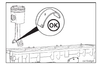
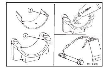
Install the upper bearing shell in the connecting rod. If used bearing shells are to be installed, each bearing shell must be installed in its original location.
NOTE: The tang (1) of the bearing shell must be in the slot (2) of the rod.
Use clean Lubriplateா 105 or its equivalent to lubricate the bearing shell.
Apply a heavy film of clean 15W-40 oil to the liner.
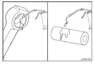
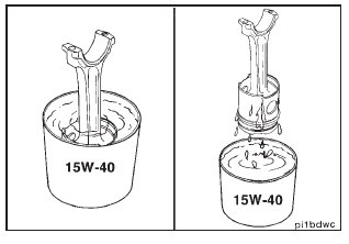
Put the piston and the ring assembly in a container of clean 15W-40 oil.
Remove the piston and the ring assembly from the container. Allow the excess oil to drain from the piston.
Install connecting rod guide pins, Part No. 3375601.
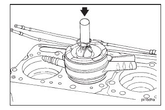
Use piston ring compressor, Part No. 3822736, to compress the rings.
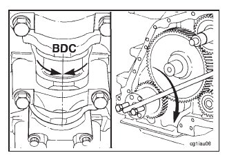
Rotate the crankshaft to position the journal for the connecting rod at bottom dead center (BDC).
NOTE: Use the barring tool and two capscrews to rotate the crankshaft.
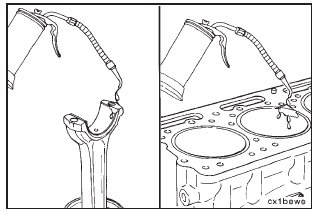
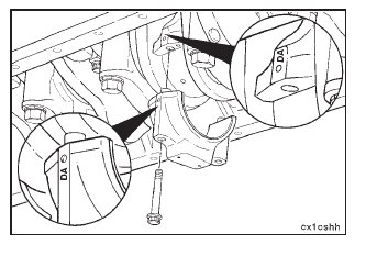
NOTE: The tang of the connecting rod must be toward the camshaft side of the cylinder block. The piston cooling nozzles must be removed prior to installation of the piston and connecting rod assemblies.
Install the connecting rod in the cylinder liner, and push the piston down. If the piston does not move freely, remove the piston. Inspect for broken or damaged rings.
When installing the connecting rod, pay close attention to make sure the rod is aligned with the rod journal. If the rod is misaligned, it can bind or scrape the crankshaft connecting rod journal side walls.
Use the guide pins to pull the connecting rod against the crankshaft.
Remove the guide pins.
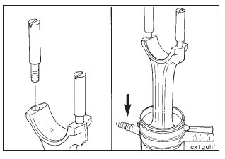
Install the bearing in the connecting rod cap.
NOTE: The tang (2) of the bearing must be in the slot (1) of the cap.
Lubricate the bearing shell with Lubriplateா 105 or its equivalent. Lubricate the connecting rod capscrew threads and the washer face with 140W oil.
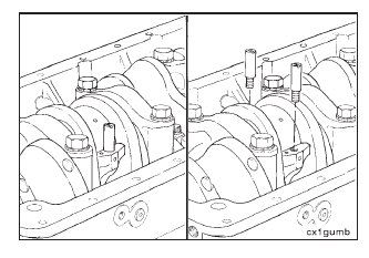
Install the connecting rod caps and the capscrews.
Tighten the rod capscrews in alternating sequence to the following torque values:
• Tighten to 102 N•m [75 ft-lb].
• Tighten to 264 N•m [195 ft-lb].
Measure the connecting rod side clearance. The side clearance must be between 0.114 mm [0.0045-inch] and 0.51 mm [0.020-inch].
NOTE: The connecting rod must move freely from side to side on the crankshaft journal. If the rod does not move freely, remove the rod cap and make sure the bearing shells are the correct size. Check for dirt or damage on the crankshaft and the bearing shells.