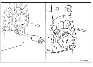
Install two 5/8-18 x 4-inch guide studs in the cylinder block to help support and align the housing during installation.
If a wet-type flywheel housing is being installed, do the following:
1. Install a new o-ring on the rear cover. Use vegetable oil to lubricate the o-ring.
2. Install 11 rectangular sealing rings in the capscrew dowel pin counterbores in the flywheel housing. Use gasket adhesive to fasten the sealing rings to the housing.

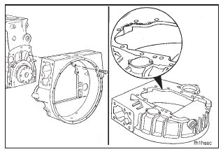
Install the flywheel housing over the guide studs.
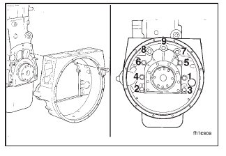
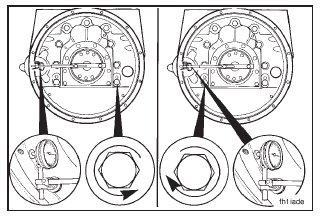
Install the capscrews, and tighten in the sequence shown.
Torque Value: 203 N•m
[150 ft-lb]
Bore Alignment – Measurement
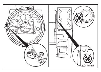
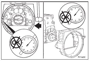
Use chalk to mark the housing at the 12:00 o’clock, 3:00 o’clock, 6:00 o’clock, and 9:00 o’clock positions.
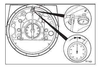
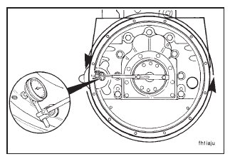
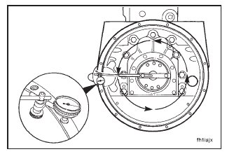
Use dial gauge indicator (1), Part No. 3376050, and dial gauge attachment (2), Part No. ST-1325, to measure the bore alignment.
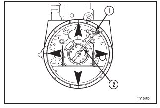
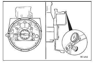
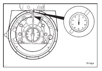
Attach a dial indicator to the crankshaft as shown.
NOTE: The indicator arm must be rigid for an accurate reading. It must not sag.
Put the indicator at the 12:00 o’clock position. Adjust the dial indicator until the needle points to ‘‘0.’’
Rotate the crankshaft one complete revolution in a clockwise direction (viewed from the front of the engine).
Record the indicator reading at three different positions: 3:00 o’clock, 6:00 o’clock, and 9:00 o’clock.
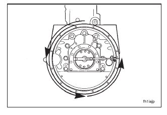
Continue rotating the crankshaft until the dial indicator is at the 12:00 o’clock position.
Check the dial indicator to make sure the needle still points to ‘‘0.’’
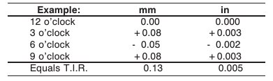
Determine the total indicator runout (T.I.R.) as follows:
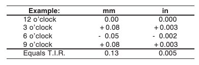
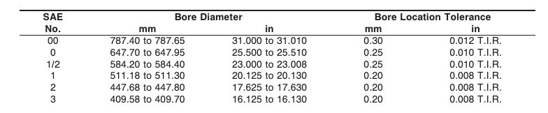
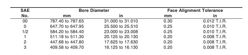
The maximum allowable total indicator runout (T.I.R.)depends on the diameter of the housing bore. See the following chart:
If the bore alignment does not meet the specifications, loosen the housing capscrews. Tighten the capscrews again, and measure the bore alignment again.
If the alignment is not within specifications and the bore is round, the housing can be shifted. Refer to Section 16.
If the alignment is not within specifications and the bore is not round, the housing must be replaced.
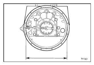
Face Alignment – Measurement
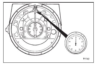
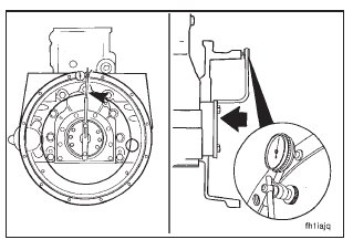
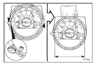
Install the dial indicator as shown.
Put the tip of the dial indicator gauge against the flywheel housing surface.
Rotate the crankshaft until the dial indicator is at the 12:00 o’clock position.
Push the crankshaft toward the front of the engine. Adjust the dial on the indicator until the needle points to ‘‘0.’’
NOTE: The crankshaft must be pushed toward the front of the engine to remove the crankshaft end clearance each time a point is measured.
Rotate the crankshaft in a clockwise direction (viewed from the front of the engine).
Record the indicator reading at three different positions: 3:00 o’clock, 6:00 o’clock, and 9:00 o’clock.
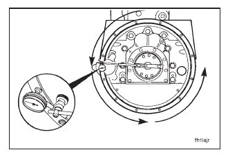
Continue rotating the crankshaft until the dial indicator is at the 12:00 o’clock position.
Check the dial indicator to make sure the needle still points to ‘‘0.’’
Determine the total indicator runout (T.I.R.) as follows:
The maximum allowable total indicator runout (T.I.R.) depends on the diameter of the housing bore. See the following chart:
If the alignment is not within specifications, remove the housing. Check for nicks, burrs, or foreign material between the block and the housing.
Check the alignment again. If the alignment is not within specifications, the block or the housing is not machined correctly.