Caution: Incorrect installation will block oil flow to the rocker levers and the cam followers resulting in severe
damage to the engine. Refer to the numbers stamped on the bushings to determine the correct cylinder block
cam bore locations in which the bushings are to be installed.
Install the camshaft bushings in the following order: No. 7, No. 6, No. 5, No. 4, No. 3, No. 2, and No. 1.

Bushing (No. 7) – Installation
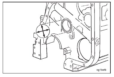
An alignment pointer, Part No. 3823635, is used to align the cam bearing oil holes with the oil holes in the block.
To use, mount the bearing on the driver. Place the alignment pointer against the machined side of the block at the
cam follower holes with the end of the rod at the top of the bearing. Rotate the cam bearing until the seam of the
bearing is at the end of the rod. Press the cam bearing in as described.

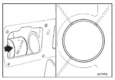
Install the bushing marked No. 7 on the driver with the location notch to the rear of the engine and at the 6:00
o’clock position.
Push the bushing into the bore until the oil holes in the bushing are aligned with the drillings in the bore.

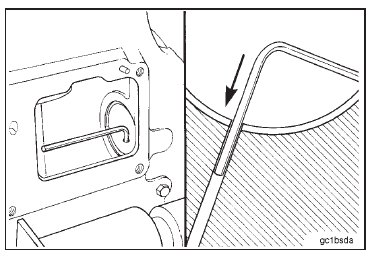
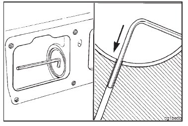
Use a 2.39 mm [0.094-inch] diameter rod or a 3/32-inch hexagon wrench to check the position and the location of
the oil hole in the bushing and the cylinder block.
The rod must pass through the oil holes in the bushing and into the oil supply drillings in the cylinder block.
Bushings (No. 6 through No. 2) – Installation
An alignment pointer, Part No. 3823635, is used to align the cam bearing oil holes with the oil holes in the block.
To use, mount the bearing on the driver. Place the alignment pointer against the machined side of the block at the
cam follower holes with the end of the rod at the top of the bearing. Rotate the cam bearing until the seam of the
bearing is at the end of the rod. Press the cam bearing in as described.

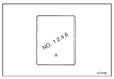
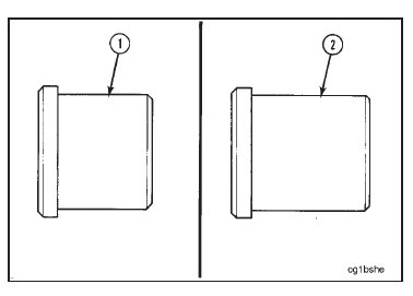
Use bushing driver (1), Part No. 3375861, to install bushings No. 1, No. 2, No. 4, and No. 6.
Use bushing driver (2), Part No. 3376412, to install bushings No. 3 and No. 5.
Install the tool assembly through the camshaft bore until the driver is in the cavity between the bores where the
bushing is to be installed.
Install the bushing guide into the camshaft bore next to the bore where the bushing is to be installed.

An alignment pointer, Part No. 3823635, is used to align the cam bearing oil holes with the oil holes in the block.
To use, mount the bearing on the driver. Place the alignment pointer against the machined side of the block at the
cam follower holes with the end of the rod at the top of the bearing. Rotate the cam bearing until the seam of the
bearing is at the end of the rod. Press the cam bearing in as described.
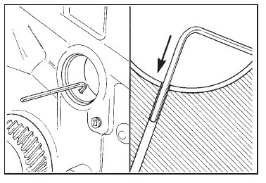
Use a 2.39 mm [0.094-inch] diameter rod or a 3/32-inch hexagon wrench to check the position and the location of
the oil hole in the bushing and the cylinder block.
The rod must pass through the oil holes in the bushing and into the oil supply drillings in the cylinder block.
Bushing (No. 1) – Installation
NOTE: Camshaft bushing guide, Part No. ST-1228-6, is not used to install the No. 1 bushing.
An alignment pointer, Part No. 3823635, is used to align the cam bearing oil holes with the oil holes in the block.
To use, mount the bearing on the driver. Place the alignment pointer against the machined side of the block at the
cam follower holes with the end of the rod at the top of the bearing. Rotate the cam bearing until the seam of the
bearing is at the end of the rod. Press the cam bearing in as described.

Use a 2.39 mm [0.094-inch] diameter rod or a 3/32-inch hexagon wrench to check the position and the location of
the oil holes in the bushing and the cylinder block.
The rod must pass through the oil holes in the bushing and into the oil supply drillings in the cylinder block.
Measure the inside diameter of the installed camshaft bushings.
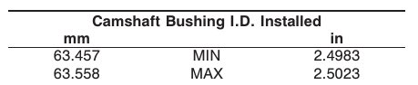
NOTE: If any of the bushings is not within specification, the bushing must be replaced.