
1 Electromagnetically operated fuel pressure control valve
2 Valve seat
3 Valve ball
4 Coil
5 Armature
6 Compression spring
7 Pin
NOTE: During repair, the high pressure control valve may not be removed from the high pressure pump. The pump may only be replaced as a complete unit.
The fuel pressure control valve is flanged directly onto the high pressure pump.
The high pressure control valve regulates the fuel pressure at the high pressure outlet port of the high pressure pump and consequently the pressure in the fuel rail. In addition, pressure fluctuations arising during fuel supply and the injection process are compensated by the fuel pressure control valve.
The fuel pressure control valve is actuated by the PCM so that the optimum fuel pressure is present in the fuel rail for all engine operating states.
The fuel pressure control valve is operated electromagnetically and is closed and opened in a controlled manner via pulse-width modulated signals from the PCM. The variable actuation of the valve is a function of driver request, fuel pressure requirement and engine speed.
The required pressure in the fuel rail during starting must be at least 150 bar. Below this minimum pressure, fuel injector needle lift is not possible. The engine cannot be started, it cuts out.
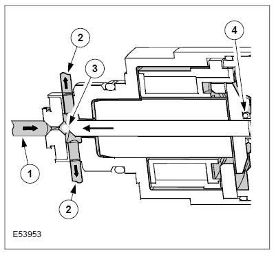
1 Fuel pressure at the high pressure outlet port of the high pressure pump
2 To fuel return
3 Valve ball
4 Compression spring (partial section shown)
Fuel pressure control valve not actuated
• The valve ball is only operated via the spring force. This maintains a low fuel pressure (pmin) at the high pressure outlet port of the high pressure pump to the fuel rail. The fuel pressure control valve is open.
Note: In the case of a defective fuel pressure control valve (e.g. if the valve is permanently de-energized) a fuel rail pressure of only 50 bar is achieved during the starting phase. This holding pressure is a result of the closing force of the compression spring when the valve is de-energized.
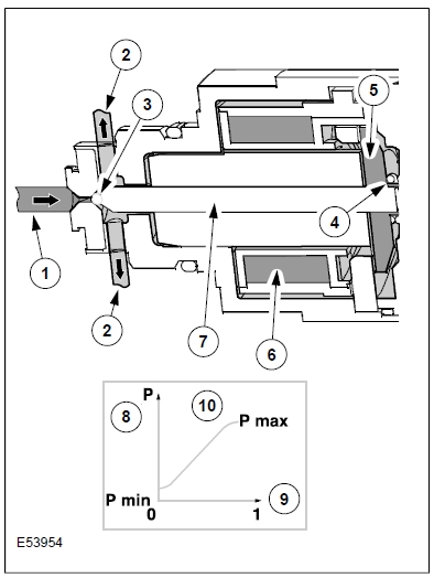
1 Fuel pressure at the high pressure outlet port of the high pressure pump
2 To fuel return
3 Valve ball
4 Compression spring
5 Armature
6 Coil energized
7 Pin
8 High fuel pressure
9 Valve control current
10 Fuel pressure control valve characteristic curve
Fuel pressure control valve actuated by PCM
• The energized coil attracts the armature. The armature transfers the magnetic force to the valve ball via the pin.
• The force with which the armature is attracted, and consequently the pressure on the valve ball, is proportionate to the valve control current. The fuel pressure control valve closes.
• In the case of maximum PWM actuation, the maximum required fuel pressure (depending on actuation of the fuel metering valve) is adjusted in the fuel rail.
Effects of faults
The fuel metering valve operates together with the high pressure control valve and the fuel pressure sensor at the fuel rail in a closed-loop control circuit. In the case of serious faults, for example a short or open circuit, fuel injection no longer takes place as the fuel pressure is limited to 50 bar owing to the de-energized fuel pressure control valve.
In the case of various control faults in the PCM, a limited operation program is activated, permitting continuation of the journey to the next workshop under restricted conditions.
Diagnosis (fuel metering valve and fuel pressure control valve)
The EOBD requirement demands the detection of faults when determining the injected fuel quantity and fuel injection timing. These parameters can have serious effects on the exhaust gas emissions.
The determination of the fuel injection timing is established via the crankshaft position.
The injected fuel quantity results from the engine speed and the opening time of the fuel injector, depending on the fuel pressure in the fuel rail.
Monitoring of the fuel pressure is a function determined by the interaction of the fuel metering valve (adjusts the delivery quantity for the fuel rail), the fuel pressure control valve (regulates of the fuel pressure to the fuel rail) and the fuel pressure sensor (provides feedback regarding the actual fuel pressure in the fuel rail).
The Siemens diagnostic system classifies faults in the fuel metering valve either
• as control faults (in this case the fuel pressure is limited to a safe range) or
• as malfunctions (in this case, the engine is switched off by the PCM), for example short or open circuit.
The following monitoring is performed in the context of EOBD:
• Shorts and open circuit (no power consumption at the relevant valve).
• Power consumption of the fuel metering valve/fuel pressure control valve or pulse-width modulation from the PCM outside the limit range. From the output shape of the pulse width modulated signals, the monitoring system identifies (by comparing it with the target map data) whether the actuation is within the limits. Power consumption of the respective components provides information to the PCM as to whether the relevant component is operating correctly or not.
• Plausibility check for correct closing of the fuel metering valve.
• Position (actuation) of the fuel metering valve deviates to an impermissible extent from the position (actuation) of the fuel pressure control valve.
• Sticking fuel pressure control valve.
• Adjustment of the map data for the fuel metering valves reaches the maximum (impermissible deviation of position with regard to map data; in order to achieve the required fuel pressure, the fuel metering valve must open to an impermissible extent).