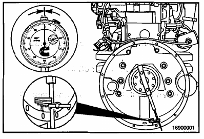
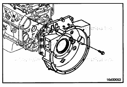
Attach the dial indicator gauge, Part Number 3376050, to the crankshaft. Use mounting tool, Part Number ST1325,
to attach the dial indicator to the crankshaft as illustrated.
NOTE: The dial indicator can be mounted by any method that holds the extension bar of the indicator rigid, so it
does not sag. If the bar sags or the indicator slips, the readings obtained will not be accurate.
Position the indicator in the 6-o’clock position, and zero the gauge.
Slowly rotate the crankshaft. Record the readings obtained at the 9-o’clock, 12-o’clock, and 3-o’clock
positions as A, B, and C in the concentricity work sheet.
Check zero at the 6-o’clock position. If it does not, the readings will be incorrect and the procedure will have to
be redone.
The values for A, B, and C can be positive or negative.
See the accompanying figure to determine the correct sign when recording these values.
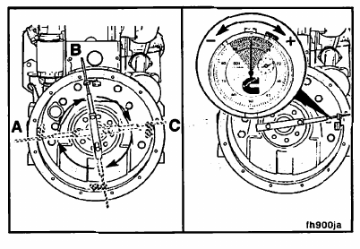
Rotate the crankshaft until the dial indicator is at the 12- o’clock position and zero the gauge.
Using a pry bar, raise the rear of the crankshaft to its upper limit. Record the value as D on the concentricity work
sheet. This is the vertical bearing clearance adjustment, which will always be positive.

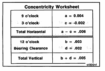
Create a concentricity work sheet as illustrated to determine the values for the “total vertical” and “total
horizontal” values.
NOTE: The values listed in the concentricity work sheet illustrated are for example only and are listed in inches.
The actual numbers measured may differ.
Input the values recorded for A, B, C and D into the concentricity work sheet.
The total horizontal is the 9-o’clock reading, A, minus the 3-o’clock reading, C.
The total vertical is the 12-o’clock reading, B, plus the bearing clearance, D.
Example:
• Six o’clock = reference = 0
• Nine o’clock = (a) = 0.004
• Twelve o’clock = (b) = 0.003
• Three o’clock = (c) = (-0.002)
Using the work sheet and the numbers from the example, the total horizontal value equals 0.006 and the total
vertical value equals 0.005.
NOTE: Use the corresponding chart for the SAE 1 , 2 or 3 flywheel housings being measured.
Using the illustration, mark the total horizontal value on the horizontal side of the chart and the total vertical on the
vertical side of the chart.
Use a straightedge to find the intersection point of the total horizontal and total vertical values. The intersection point must fall within the shaded area for the flywheel housing concentricity to be within specification.
Using the total horizontal and total vertical values from the previous example, the intersection point falls within the
shaded area. Therefore, the flywheel housing concentricity is within specification.
NOTE: Make sure to use the correct total indicator reading (TIR) specifications for the flywheel housing being
measured when comparing measurements.
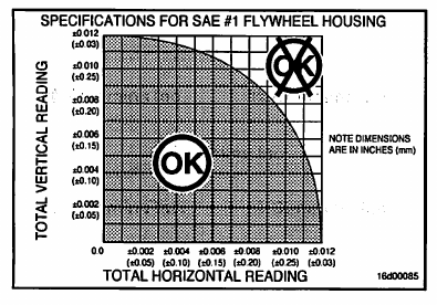
Chart for an SAE 2 flywheel housing.
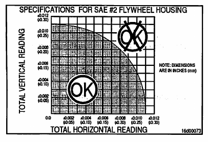
Chart for an SAE 3 flywheel housing.

For rear gear train engine, if the bore alignment is out of specification:
1. Determine if the flywheel housing, rear gear housing, or cylinder block has recently been replaced. If any of
these components have been replaced, remove and inspect/replace the component.
2. If the flywheel housing, rear gear housing or cylinder block have not been recently replaced. Remove the
flywheel housing. Inspect the rear gear housing and flywheel housing mounting surfaces. If no damage is
found, remove the rear gear housing and inspect the cylinder block and rear gear housing mounting surfaces.
For front gear train engine, if the bore alignment is out of specification:
The ring dowels must be removed and the flywheel housing repositioned.
Use the dowel pin extractor service tool, Part Number 3163720, to remove the dowel pins from the block.
NOTE: The ring dowels are not required to maintain concentricity of the housing; the clamping force of the
cap screws holds the housing in place.

After the ring dowels are discarded, install the flywheel housing on the engine following the Install Step of this
procedure, but do not torque the cap screws. Tighten the cap screws enough to hold the flywheel housing in place,
but loose enough to allow small movement when struck lightly with a rubber mallet.
Check the bore alignment. When bore alignment is within specification, tighten the cap screws to the specified
torque value outlined in the Install Step of this procedure.
