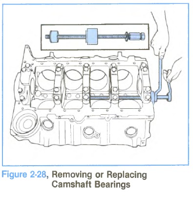
• REMOVAL (FIGURE 2-28)
Camshaft bearings can be replaced while engine is disassembled for overhaul.
1. With camshaft and crankshaft removed, drive camshaft rear plug from cylinder block.
2. Using Tool J-6098 with nut and thrust washer installed to end of threads, index pilot in camshaft front bearing and install puller screw through pilot.
3. Install remover and installer tool J-6098-11 for #2, 3,
4 bearing with shoulder toward bearing, making sure a sufficient amount of threads are engaged.
4. Using two wrenches, hold puller screw while turning nut. When bearing has been pulled from bore, remove remover and installer tool and bearing from puller screw (Figure 2-28).
5. Remove remaining bearings (except front and rear) in the same manner. It will be necessary to index
pilot in camshaft rear bearing to remove the rear intermediate bearing.
6. Assemble remover and installer tool J-6098-11 for #1 and J-6098-12 for #5 bearing on driver handle and remove camshaft front and rear bearings by driving towards center of cylinder block (Figure 2-29).
• INSTALLATION
The camshaft front and rear bearings should be installed first. These bearings will act as guides for the pilot and center the remaining bearings being pulled into place.
1. Assemble remover and installer tool on driver handle and install camshaft front and rear bearings by
driving towards center of cylinder block.
2. Using Tool Set J-6098 with nut then thrust washer installed to end of threads, index pilot in camshaft front bearing and install puller screw through pilot.
3. Index camshaft bearing in bore (with oil hole aligned as outlined below), then install remover and installer
tool on puller screw with shoulder toward bearing.
All five bearings must have an oil hole at the approximate 4 o’clock position when viewed from the front with the block in an upright position.
The seam in the bearing must always be located in the upper half of the block face.
The front bearing has an additional oil hole which will be located between the 12 and 1 o’clock position. This bearing also has a notch which must be positioned towards the front of the block.
This procedure will ensure that the oil supply to the bearings will enter prior to the high load zone which is near the bottom of the bore.
