General Information
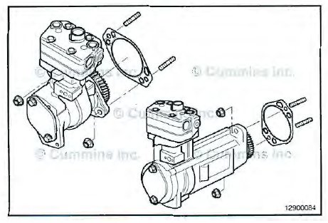
Cummins® engines are equipped with a variety of air compressors, including a two cylinder version. This
procedure will cover the removal, cleaning , inspection, and installation of Wabco'”‘ and Knorr-Bremse'”‘ brands of
air compressor.
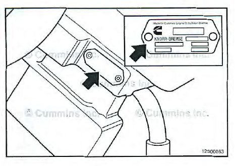
To determine what brand air compressor a specific engine has, look on the air compressor data plate, usually located
on the side of the air compressor.
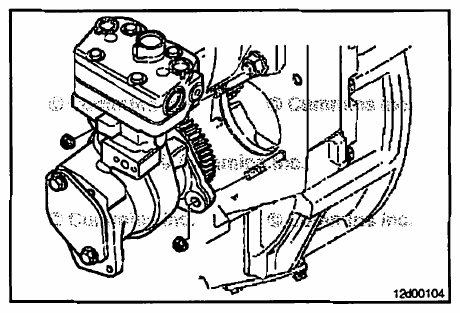
The air compressor can be mounted in one of two configurations , depending on the application; they are a
high mount and low mount location on the rear gear housing.
In general, the removal and installation procedures for high mount and low mount air compressors are the same.
The air compressor also has mounting provisions for driving an accessory drive, such as a power steering/ hydraulic pump.
Assemble
Wabco'”‘
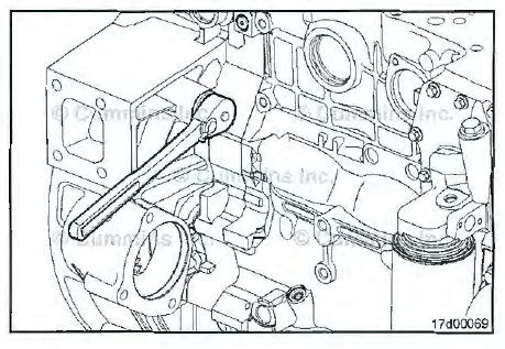
Install the cylinder block mounting bracket and mounting fasteners.
Tighten the mounting fasteners finger-tight.
Time
NOTE: To make sure the air compressor does not contribute to engine vibrations when installed, the air
compressor must be properly timed to the engine .
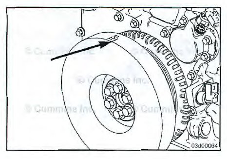
Use the barring tool , Part Number 3824591 , or equivalent, to rotate the crankshaft until the number 1 is at top dead
center (TDC).
Align the vibration damper so that the TDC indicator on the vibration damper is at the 12-o clock position.
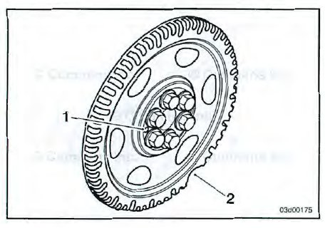
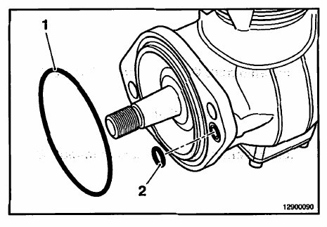
NOTE: If no TDC mark is present on either the vibration damper or the crankshaft speed indicator ring, align the large gap in the crankshaft speed indicator ring to the 5-oclock position (2). The dowel pin can also be visible in the 9-o clock position (1).
Wabco”‘
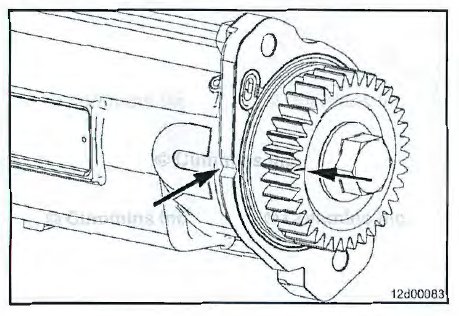
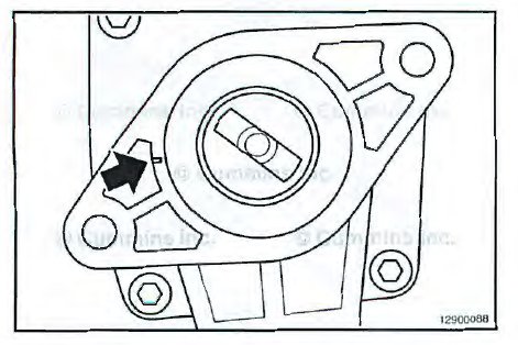
Set the timing mark on the air compressor gear to the 9 o clock position when looking at the gear. It must point at the casting depression on the side of the air compressor mounting flange.
Knorr-Bremse
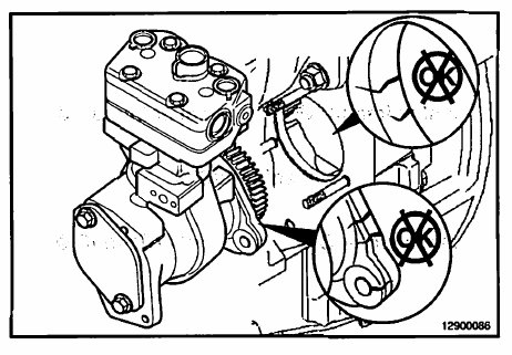
Set the air compressor to top dead center (TDC) by aligning the two timing marks on the rear of the compressor and on the rear drive.
Install
WabcoTM
For Wabcom air compressors use the following procedure:
Prior to installing the air compressor, identify which gasket is going to be installed so that, if necessary, the gasket
can be properly oriented.
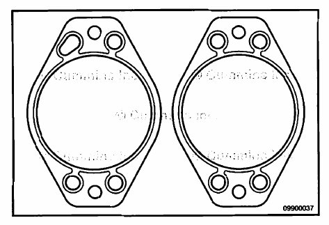
The are two types of accessory drive cover gaskets:
• Three round oil supply passages and one elongated oil supply passage
• Four round oil supply passages
It is preferred that, when installing the air compressor, the gasket with the four round oil supply passages be used.
The gasket can be installed in any orientation. If only the gasket with the one elongated oil supply passage is available, install the gasket so that the elongated oil supply passage is not over the oil supply port in the rear gear housing.
NOTE: Rotate the engine slightly before or after TDC, if necessary, to properly engage the compressor drive gear
with the camshaft gear.
With the engine set at TDC, install the air compressor and a new gasket onto the rear gear housing, engaging the air
compressor drive gear with the camshaft gear.
Install the air compressor mounting fasteners and tighten.
Install the air compressor mounting fasteners and finger tighten the capscrews.
Install the air compressor support bracket.
Install the air compressor support bracket to cylinder block mounting bracket mounting capscrews and finger-tighten.
Install the air compressor support bracket mounting capscrews and finger-tighten.

NOTE: For low mount designs, it is important to make sure of appropriate positioning of the air compressor relative to
the engine block in order to minimize gear lash. This will help minimize noise from the gear train during normal
engine operation.
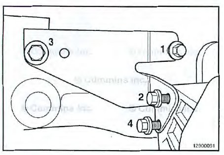
Loosen the six air compressor mounting capscrews.
Push the air compressor assembly as close to the engine block as possible and tighten the upper mounting
capscrew (1 ).
Torque Value: 77 N•m [ 57 ft-lb ]
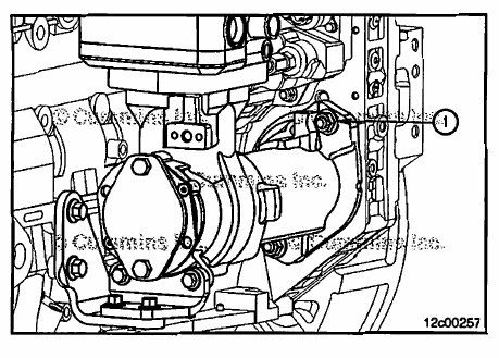
Using the upper mounting capscrew as a pivot point, rotate the air compressor assembly in the clockwise
direction when viewed from the front of the engine.
NOTE: This action should slightly move the bottom of the air compressor assembly towards the engine block.
Tighten the lower mounting capscrew (1).
Torque Value: 77 N•m [ 57 ft-lb ]

Verify the air compressor support bracket is contacting the cylinder block support bracket. Adjust the brackets as
necessary. If necessary, loosen the cylinder block support bracket to align the components.
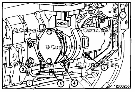
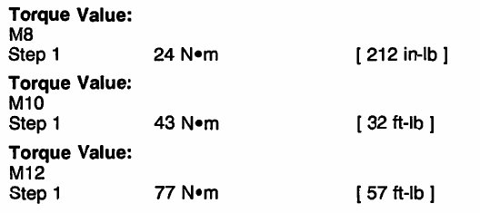
Tighten the air compressor support bracket mounting capscrews first (1 ).
Tighten the compressor support bracket cylinder block support bracket mounting capscrews second (2).
If loosened, tighten the cylinder block support bracket cylinder block mounting capscrews third (3).
Knorr-Bremse TM
NOTE: Rotate the engine slightly before or after TDC, if necessary, to properly engage the compressor teeth on
the camshaft gear.
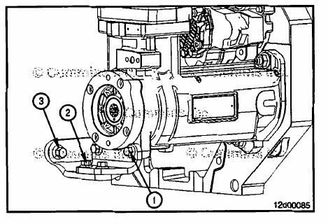
Apply clean 15W-40 engine oil or Assembly Lube, Part Number 3163087, or equivalent, to both a-ring recesses;
this will help keep the a-rings in the correct location while installing the compressor.
Install new a-rings onto the air compressor.
Locate both the large (1) and small (2) a-rings as shown in the illustration at right into the recesses; making sure they
are both located correctly.
With the engine set at TDC, install the air compressor, engaging the air compressor drive gear with the camshaft gear.
Install the air compressor mounting fasteners and tighten.
Torque Value: 77 N•m [57 ft-lb]
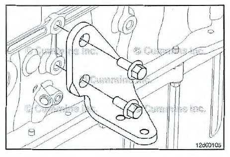
Install the four air compressor support bracket mounting capscrews and finger-tighten .
Tighten the air compressor support bracket mounting capscrews in the sequence shown.
Torque Value: 24 N•m [ 212 in-lb]