
Purpose
To determine if the ICP system is providing enough hydraulic pressure to operate the injectors
Tools
• EST with MasterDiagnostics® software
• EZ-Tech® interface cable
• ICP System Test Adapter
• Oil sample line with inline shut-off valve
• Socket or wrench (EOT sensor)
Monitoring ICP and BCP using EST
NOTE: If an EST is not available, use alternate test procedures following this test.
1. See “DT 466 Performance Specifications” – Appendix A (page 595) or “DT 570 and HT 570
Performance Specifications” – Appendix B (page 619) for specifications and record on Diagnostic Form.
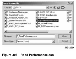
2. Open D_RoadPerformance.ssn to monitor engine operation.
3. Turn the ignition switch to ON. Do not start engine.
Monitor KOEO Inject Ctrl Press (ICP). Record results on Diagnostic Form.
• If injection control pressure is higher than specification, the ICP sensor or circuitry may be the cause.
This will cause a lower than normal injection control pressure command. See “ICP Sensor” in Section 7.
• If injection control pressure is in KOEO specification, continue to step 4.
4. Run engine at low idle, monitor ICP, and record reading on Diagnostic Form.
NOTE: BCP value should be 0 psi. However, BCP values may fluctuate as much as 345 kPa (50 psi). Electromagnetic Interference (EMI) or ground shift can cause an insignificant voltage shift that does not indicate a problem.
5. Run engine at high idle, monitor ICP, and record initial results on Diagnostic Form. Continue to run the engine at high idle for 2 minutes, monitor ICP, and record the 2 minute results on Diagnostic Form. Compare the two ICP readings. ICP that rises above the specification at any point during the two minutes, indicates oil aeration.
• If ICP is high or unstable for low or high idle, do step 6.
• If BCP is above zero when engine brake is inactive, diagnose BCP sensor, circuit, and engine brake components.
• If ICP is to specification, continue with Test 11 Injector Disable.
NOTE: Engine fluids, oil, fuel, and coolant, can be a threat to the environment. Never dispose of engine
fluids by putting them in the trash, pouring them on the ground, in the sewers, in streams or bodies of water.
Collect and dispose of engine fluids according to local regulations.
6. Turn off engine.
7. Use the ICP system test adapter and inline shut-off valve to make a test line assembly to take oil sample.
NOTE: The mechanic is expected to keep the test line for future diagnostics. Expense the test line as an essential tool and keep it with other diagnostic tools. Warranty will not cover the cost of the test line.
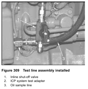
8. Remove EOT sensor from EOT port. Oil will spill out. Quickly install test line assembly.
9. Run engine at high idle for 2 minutes.
10. Return engine to low idle, take oil sample, and check for aerated oil.
11. Record results on Diagnostic Form.
• If oil is aerated, a large quantity of air bubbles mixed throughout the oil, or foam build up on top of the oil will be seen. Correct condition.
• If oil is not aerated, disconnect ICP sensor and check engine stability. If problem is corrected, see “ICP Operational Voltage Checks” in Section 7.
• If ICP is still high or unstable, replace IPR following procedures in Engine Service Manual and retest.
Possible Causes
Low injection control pressure
• Injection control pressure system leakage
• Failed IPR wiring (power and control)
• Failed IPR valve
• Failed injector
• Cracked or porous high-pressure rail
• Injector oil inlet adapter O-rings
• Injector oil inlet adapter
• O-ring for high-pressure oil rail
• End plugs in high-pressure oil rail
• Low oil pressure
• Inoperative high-pressure oil pump
• Failed ICP sensor circuit
• Failed ICP sensor
• Inoperative brake shut-off valve of Diamond Logic® engine brake
• Brake pressure relief valve (optional)
If relief valve is leaking, the brake shut-off valve is suspect.
• If ECM detect low boost pressure, an incorrect feedback signal from APS or the ICP sensor, the ECM commands the IPR valve to reduce injection control pressure.
• High injection control pressure
• Aerated lube oil
• Bias high ICP sensor – low duty cycle
• Erratic injection control pressure
• ICP sensor
• IPR wiring
• IPR valve
• Middle seal IPR valve
• Brake control pressure
• Failed BCP sensor circuit
• Failed BCP sensor
• Inoperative brake shut-off valve of Diamond Logic® engine brake
• Brake control pressure system leakage
Monitoring ICP using VC Gasket Breakout Harness
NOTE: Do this procedure, if an EST is not available.
This is an alternate method.
Tools
• VC Gasket Breakout Harness
• DMM
• ICP System Test Adapter
• Oil sample line with inline shut-off valve
• Clear container (for oil sample)
• Socket or wrench (EOT sensor)

1. See “DT 466 Performance Specifications” – Appendix A (page 595), “DT 570 and HT 570 Performance Specifications” – Appendix B (page 619) or Section 7 “Operational Voltages Checks” – for specifications and record on Diagnostic Form.
2. Disconnect engine harness connector from valve cover gasket for ICP sensor and do steps 3 to 10.

3. Connect VC Gasket Breakout Harness to the pass-through connector for ICP sensor and engine harness.
4. Use DMM to measure ICP.
• Connect POS to green (signal circuit) and NEG to black (ground circuit).
5. Turn the ignition switch to ON. (Do not start engine.) Measure KOEO ICP signal voltage and record on Diagnostic Form.
• If ICP voltage is higher than specification, the ICP sensor or circuitry may be at cause. This will cause a lower than normal injection control pressure command. See “ICP Sensor” in Section 7.
• If ICP voltage is in KOEO specification, continue to step 6.
6. Run engine at low idle, measure ICP signal voltage, and record on Diagnostic Form.
• If ICP is high or unstable for low or high idle, do step 8.
• If ICP is in specification, continue with Test 11 Injector Disable.
7. Run engine at high idle, monitor ICP, and record initial results on Diagnostic Form. Continue to run the engine at high idle for 2 minutes, monitor ICP, and record the 2 minute results on Diagnostic Form. Compare the two ICP readings. ICP that rises above the specification at any point during the two minutes, indicates oil aeration.
• If ICP is high or unstable for low or high idle, do step 8.
• If ICP is in specification, continue with Test 11 Injector Disable.
NOTE: Engine fluids, oil, fuel, and coolant, can be a threat to the environment. Never dispose of engine
fluids by putting them in the trash, pouring them on the ground, in the sewers, in streams or bodies of water.
Collect and dispose of engine fluids according to local regulations.
8. Turn off engine.
9. Use the ICP system test adapter and inline shut-off valve to make a test line assembly to take oil sample.
NOTE: The mechanic is expected to keep the test line for future diagnostics. Expense the test line as an essential tool and keep it with other diagnostic tools. Warranty will not cover the cost of the test line.

10. Remove EOT sensor from EOT port. Oil will spill out. Quickly install test hose assembly and capture oil sample in clear container.
11. Run engine at high idle for 2 minutes.
12. Return engine to low idle, take oil sample, and check for aerated oil.
13. Record results on Diagnostic Form.
• If oil is aerated, a large quantity of air bubbles mixed throughout the oil, or foam build up on top of the oil will be seen. Correct condition.
• If oil is not aerated, disconnect ICP sensor and check engine stability. If problem is corrected, see “ICP Operational Voltage Checks” – Section 7 (page 457).
• If ICP is still high or unstable, and engine has optional engine brake, continue to “Monitoring BCP using VC Gasket Breakout Harness.”
• If ICP is still high or unstable, and engine does not have optional engine brake, replace the IPR following procedures in Engine Service Manual and test again.
Monitoring BCP using VC Gasket Breakout Harness
NOTE: Only do this procedure if directed here from “Monitoring ICP using Gasket Breakout Harness.”
This is an alternate method when an EST is not available.
Tools
• VC Gasket Breakout Harness
• DMM
NOTE: BCP should be zero, when engine brake is inactive. However, BCP values may fluctuate as much
as 345 kPa (50 psi). Electromagnetic interference (EMI) or ground shift can cause an insignificant voltage shift that does not indicate a problem. This should be equal to KOEO BCP signal voltage.

1. Disconnect engine harness connector from the pass-through connector for the BCP sensor and do steps 2 to 6.
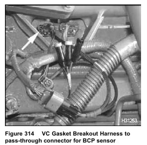
2. Connect VC Gasket Breakout Harness to the pass-through connector for the BCP sensor and engine harness.
3. Use DMM to measure BCP.
• Connect POS to green (signal circuit) and NEG to black (ground circuit).
4. Turn the ignition switch to ON. (Do not start engine.) Measure KOEO BCP signal voltage and record on Diagnostic Form.
• If BCP signal voltage is above KOEO specification, see “BCP Sensor Operational Diagnostics” in Section 7.
• If BCP signal voltage is in KOEO specification, continue to step 5.
5. Run engine at low idle and compare KOEO BCP signal voltage to low idle signal voltage.
• If BCP low idle signal voltage is more than KOEO BCP signal voltage, when engine brake is inactive, diagnose BCP sensor, circuit, and engine brake components. The BCP voltage reading should be zero psi; however, BCP values may fluctuate as much as 345 kPa (50 psi). Electromagnetic interference (EMI) or ground shift can cause an insignificant voltage shift that does not indicate a problem.
• If BCP low idle signal voltage is equal to KOEO BCP signal voltage, continue with step 6.
6.Run engine at high idle and compare KOEO BCP signal voltage to high idle signal voltage.
• If BCP high idle signal voltage is more than KOEO BCP signal voltage, when engine brake is inactive, diagnose BCP sensor, circuit, and engine brake components. The BCP voltage reading should be zero psi; however, BCP values may fluctuate as much as 345 kPa (50 psi). Electromagnetic interference (EMI) or ground shift can cause an insignificant voltage shift that does not indicate a problem.
• If BCP high idle signal voltage is equal to KOEO BCP signal voltage, there is no problem with the BCP sensor signal or the engine brake.