The APS/IVS are integrated into one component and mounted on the pedal. The accelerator pedal assembly is serviceable to the extent that the APS/IVS switch can be replaced without replacing the complete assembly.
The ECM determines the accelerator pedal position by processing input signals from the APS and the IVS.
The accelerator pedal position is one of the controlling variables in the calculation of desired injection control
pressure.
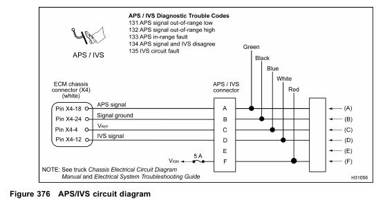
APS
The ECM supplies a regulated 5 V signal from ECM chassis connector Pin X4–4 to APS connector Pin C.
The APS returns a variable voltage signal (depending on pedal position) from the APS connector Pin A to ECM Pin X4–18. The APS is grounded at Pin B from the ECM Pin X4–24.
APS Auto-Calibration
The ECM learns the lowest and highest pedal positions by reading and storing the minimum and maximum voltage levels from the APS. In this manner the ECM auto-calibrates the system to allow maximum pedal sensitivity. The ECM auto-calibrates as the ignition switch is on, but when the ignition switch is turned OFF, these values are lost. When the key is turned on again, this process starts over. When the pedal is disconnected (or a new one is installed),
the pedal does not need to be calibrated. It simply auto-calibrates the new pedal assembly whenever the key is turned on again.
IVS
The ECM expects to receive one of two signals through the ECM chassis connector Pin X4–12 from APS/IVS connector Pin D:
• 0 V when the pedal is at the idle position.
• B+ when the pedal is depressed
The IVS receives a 12 V ignition voltage at Pin F from the ignition fuse in the power distribution box. When the pedal is not in the idle position (throttle applied), the IVS supplies a 12 V signal to the ECM.
The ECM compares APS/IVS inputs to verify when the pedal is in the idle position. If the APS signal at Pin X4–18 indicates throttle is being applied, the ECM expects to see 12 V at the IVS. If the APS signal indicates throttle is not applied, the ECM expects to see 0 V at the IVS. The timing process is critical between the APS and IVS sensors. For this reason, it is very difficult to determine if the APS/IVS assembly is working correctly when using a Digital Multimeter (DMM).
Fault Detection / Management
When the key is on, the ECM continuously monitors the APS/IVS circuits for expected voltages. It also compares the APS and IVS signals for conflict. If the signals are not what the ECM expects to see, Diagnostic Trouble Codes (DTCs) will be set.
Any detected malfunction of the APS/IVS sensor circuit will illuminate the amber ENGINE lamp. If the ECM detects an APS signal Out of Range HIGH or LOW, the engine will ignore the APS signal and operate at low idle. If a disagreement in the state of IVS and APS is detected by the ECM and the ECM determines that it is an IVS fault, the ECM will only allow a maximum of 50% APS to be commanded. If the ECM cannot discern if it is an APS or IVS fault, the engine will be allowed to operate at low idle only.
APS/IVS Diagnostic Trouble Codes (DTCs)
DTCs are read using the EST or by counting the flashes from the amber and red ENGINE lamp. NOTE: If multiple APS/IVS DTCs are present, verify the APS/IVS part number is correct for the specific vehicle model.
NOTE: If elevated low idle rpm is experienced after replacing the pedal assembly or APS/IVS sensor, and there are no DTCs present, check pedal assembly or APS/IVS sensor part numbers for correctness.
DTC 131
APS signal out-of-range low
• DTC 131 is set if the ECM detects voltage less than 0.147 V. The ECM will then restrict engine speed to idle.
• DTC 131 can be set due to a short to ground or an open V REF or signal circuits. If the condition causing DTC 131 is intermittent and the condition is no longer present, the code will become inactive and normal engine operation will resume.
• When DTC 131 is active the amber ENGINE lamp is illuminated.
DTC 132
APS signal out-of-range high
• DTC 132 is set if the ECM detects a voltage greater than 4.55 V. The ECM will then restrict engine speed to idle.
• DTC 132 can be set due to a short to VREF or B+ in the APS signal circuit.
• When DTC 132 is active the amber ENGINE lamp is illuminated.
DTC 133, 134, and 135
• The ECM checks the voltage output of the APS by comparing the APS signal to the IVS signal. APS and IVS signals can disagree in the following situations:
• The APS signal indicates the pedal is pressed down to accelerate, but the IVS signal indicates idle position.
• The APS signal indicates the pedal has been released to allow the engine to return to idle, but the IVS signal indicates off-idle position of the pedal.
If the ECM detects either of the above conditions, the ECM attempts to isolate the source of conflict and set a DTC.
DTC 133
APS in-range fault
• If the IVS signal is changing and the APS signal is constant, the ECM assumes the APS is the conflict source and sets DTC 133. The engine rpm is restricted to idle.
• When DTC 133 is active the amber ENGINE lamp is illuminated.
DTC 134
APS signal and IVS disagree
• If neither the APS or IVS is changing, or both are changing, or the ECM cannot determine the DTC in specified time, DTC 134 is set and engine rpm is restricted to idle.
• When DTC 134 is active the amber ENGINE lamp is illuminated.
DTC 135
IVS circuit fault
• If the APS is changing but IVS is constant, the ECM assumes the IVS is the conflict source and sets DTC 135. In this case the ECM limits the APS signal to a lower value that provides less than full rpm, but does not limit engine rpm to idle.
• When DTC 135 is active the amber ENGINE lamp is illuminated.
DTC 133, 134, and 135 are caused by intermittent conditions. These DTCs remain active until the vehicle has been shutdown and restarted. They do not recover without cycling the ignition switch. Later calibration versions may allow DTC recovery without cycling the ignition switch.
Tools
• EST with MasterDiagnostics® software
• EZ-Tech® interface cable
• Digital Multimeter (DMM)
• 3-Banana Plug Harness
• 500 Ohm Resistor Harness
• Breakout Box
• APS/IVS Breakout Harness
• Terminal Test Adapter Kit
The APS/IVS circuit requires the use of vehicle circuit diagrams. See truck Chassis Electrical Circuit Diagram Manual for circuit numbers, connector and fuse locations.