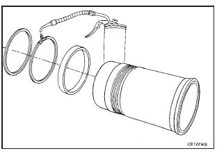
NOTE: Make sure the cylinder block and all parts are clean before assembly. If used liners are being installed again, any sealing rings removed must be installed with the same liner in the same cylinder.
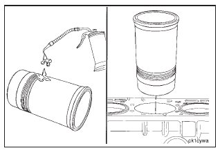
Use vegetable oil to lubricate the new liner o-rings and the crevice seals.
NOTE: Use vegetable oil to lubricate the o-rings. Do not use
lubricating oil on the o-rings. The o-rings will increase in size after they have been lubricated with oil.
Install the o-rings and the crevice seals as follows:
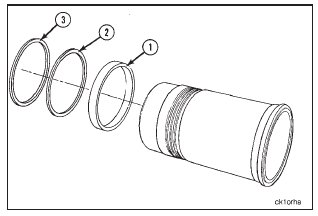
1. Install the crevice seal (1) in the top groove.
2. Install the black o-rings (2 and 3) in the center and the bottom grooves.
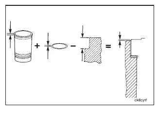
Counterbore sealing is accomplished with brass seal rings. Seal rings are available in several thicknesses. The correct thickness must be chosen to meet cylinder liner protrusion specifications.

The desired protrusion is the total sum of the thickness of the liner flange and the seal rings minus the counterbore depth.
Lubricate the crevice seal and the o-rings with vegetable oil.
NOTE: Make sure the oil does not touch the counterbore or the liner flange and that the o-rings do not move from the grooves.
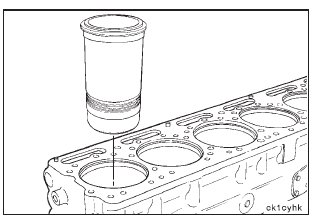
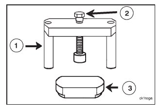
Liner installation tool, Part No. 3822953, is used to press the cylinder liner into the cylinder block. Protrusion can be checked while the liner is held down by the installation tool.
Put a sealing ring into position on the counterbore ledge.
Install the liner into the cylinder bore, slip through the sealing ring, and push down until it stops. Put the force plate (3) across the top of the liner with the step in the liner bore. Tap the top of the force plate with a soft hammer to square up and start the liner into the press fit bore.
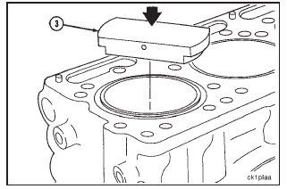
Put the installation tool bridge (1) across the liner and install the two cylinder head capscrews finger tight to hold the bridge down. Rotate the force plate until the areas where the protrusion measurements will be taken are exposed.
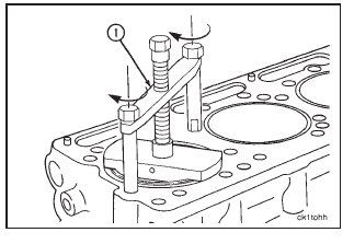
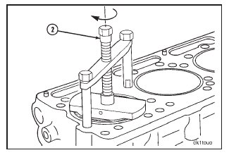
Tighten the forcing screw (2).
Torque Value: 136 N•m [100 ft-lb]
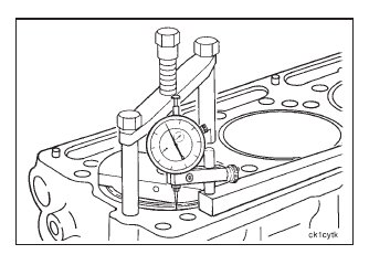
Check for correct protrusion.
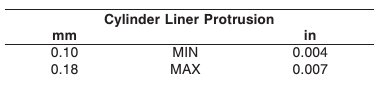
Use a depth gauge, Part No. 3823495, to measure theliner protrusion at four points 90 degrees apart. The protrusion must be from 0.10 mm to 0.18 mm [0.004-inch to 0.007-inch].

If correct liner protrusion is not attained, remove the liner from the cylinder block.
Check the following for causes of incorrect liner protrusion:
1. Check for twisted liner o-rings.
2. Incorrect liner sealing ring thickness.
3. Clean the liner flange and the cylinder block liner counterbore.
4. Inspect the liner flange for burrs.
5. Inspect the cylinder block liner counterbore for burrs.
Remove the burrs, or replace the damaged parts.

Install the liner again. Check the liner protrusion again. If protrusion is still not correct, refer to the N14 Troubleshooting and Repair Manual, Bulletin No. 3810456, Section 7, ‘‘Counterbore Ledge Measurement and Machining.’’