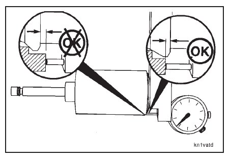
Use the N14 valve head checking tool to measure the head thickness of the valve.
NOTE: If the valve head is below the end of the tool, the valve must be replaced.
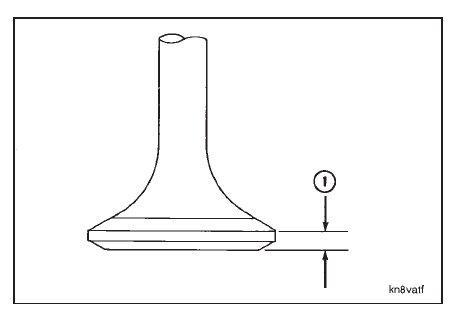
If a valve checking tool is not available, put the valve on a flat surface and measure the head thickness (1) at the
outside diameter.
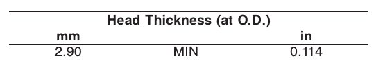
NOTE: If the valve head is worn thinner than the minimum specified, the valve(s) must be replaced.
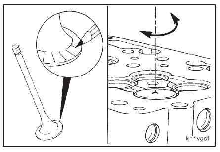
Use a lead pencil or Dykem to mark across the valve face as shown. Install the valve in the valve guide.
Hold the valve against the valve seat, and rotate the valve backward and forward three or four times. Correct contact
against the valve seat will break the marks on the valve face.
NOTE: Valves and valve seats that are correctly machined do not require the use of lapping compound to make an air
tight seal. If lapping compound is required, inspect the adjustments of the facing machine and the condition of the
grinding stone.
Install the valves in the cylinder head. Refer to ‘‘Assembly’’ under Cylinder Head – Rebuild (02-02).
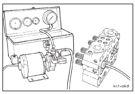
Use valve vacuum tester, Part No. ST-1257, to vacuum test the valve seating. Refer to Cylinder Head – Vacuum
Testing Valve Seating for Reuse (02-10).