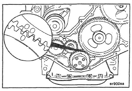
NOTE: Omit this step if the removed gear housing was installed; proceed to page 7-143 and complete the installation of the rocker levers.
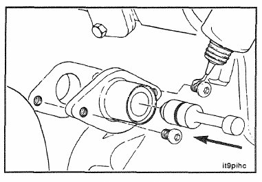
The location of the timing pin assembly on the gear housing is critical for correct engine adjustments. Follow this
procedure to install the assembly so that it corresponds to Top Dead Center (TDC), for Cylinder Number 1.
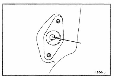
Verify that the No. 1 cylinder is at or near TDC on the compression stroke by rotating the crankshaft until the engine timing pin engages in the cam gear hole or the hole is visible through the gear housing. Disengage the timing pin.
10 mm
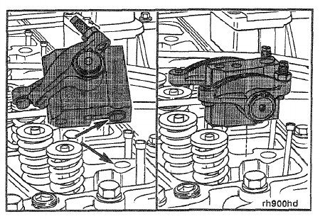
Install the rocker lever, pedestal assembly for Cylinder Number 1.
Refer to Procedure (7-03).
10 mm
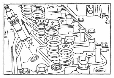
Remove the injector nozzles from all of the cylinders.
This step is important to vent the cylinders so the crankshaft can be rotated smoothly to locate TDC for Cylinder
Number 1.
18 mm
Temporarily install the crankshaft damper or crankshaft pulley.
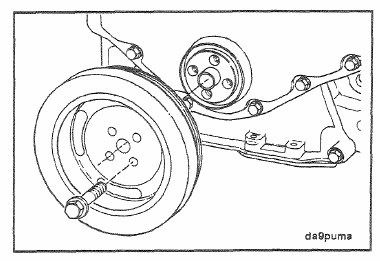
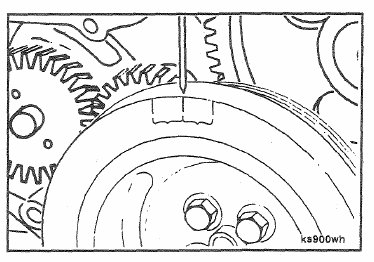
Fabricate and install a wire pointer for the front of the engine. This can be done by forming a piece of wire that
can be tightened under one of the gear housing capscrews. The wire should extend from the gear cover to a
place on the crankshaft vibration damper that is easily seen.
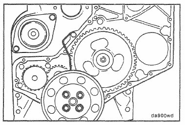
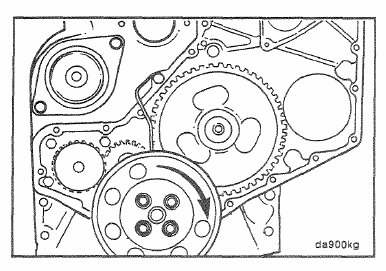
Rotate the crankshaft one-quarter revolution in the direction of normal engine rotation.
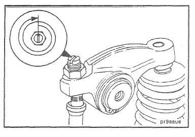
Tighten the adjusting screw for the No. 1 intake valve to zero (0) lash plus 5 turns.
Caution: Use extreme care when rotating the crankshaft.
Use o f too much force could damage the valve or push rod.
Rotate the crankshaft slowly in the opposite direction of normal engine rotation until the piston touches the intake
valve.
Mark the vibration damper at the wire pointer.
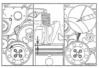
Caution: Make sure that the piston touches the intake valv® with approximately the same amount of force as in
the previous step.
Rotate the crankshaft in the direction or normal engineroation until the piston touches the intake valve.
Mark the vibration damper at the wire pointer.
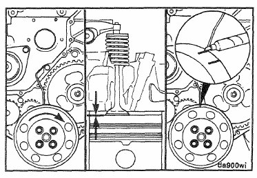
Measure the distance and mark the vibration damper at one-half the distance between the two marks. This mark
is the TDC mark.
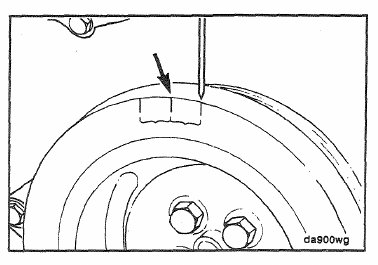
Caution: Completely loosen the intake valve adjusting screw. Failure to do so will result in damage to the intake
valve or push rod when the crankshaft is rotated.
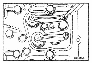
Rotate the crankshaft in the direction of normal engine rotation until the pointer is aligned with the TDC mark,
then rotate the crankshaft one additional revolution.

T-25 Torx
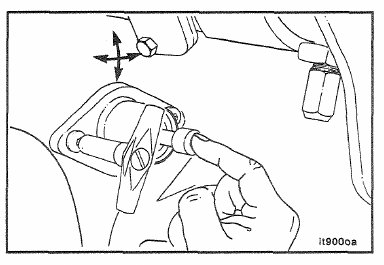
Hold the timing pin in the hole to align the housing.
Torque Value: 5 N®m [4 ft-lb]
Install the remaining rocker lever pedestal assemblies.
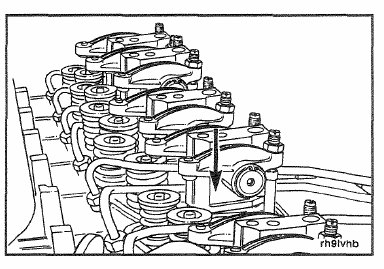
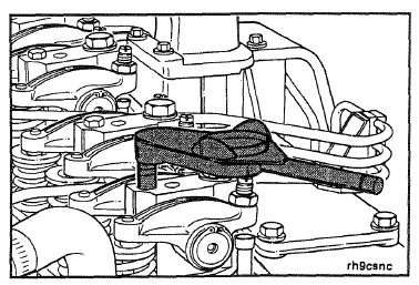
10 mm
Tighten the rocker lever pedestal mounting capscrews.
Refer to Procedure (7-03).
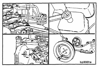
Complete the installation of the removed components.
• Adjust the valves. Refer to Procedure (7-03).
• Injectors. Refer to Procedure (5-13).
• Fuel injection pump. Refer to Procedures (5-35) or (5-37).
• Gear cover. Refer to Procedure (7-18).
• Vibration damper. Refer to Procedure (7-15).
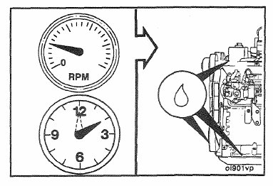
Operate the engine at idle for 5 to 10 minutes and check for leaks and loose parts.