Use vegetable oil to lubricate the injector sleeve o-rings.
Install the o-ring (1) into the groove of the injector sleeve bore.
Use an injector sleeve driver, Part No. ST-1227, to push the injector sleeve into the cylinder head. Do not hit the
driver with a hammer. Remove the sleeve driver.
Install an injector sleeve holding tool, Part No. ST-1179, into the injector sleeve and tighten the nut.
Torque Value: 60 N•m [45 ft-lb]

Install the injector sleeve driver against the holding tool mandrel. Hit the driver two moderate blows with a ham-
mer to seat the sleeve in the bore.
Remove the driver, and tighten the injector sleeve holding tool nut again.
Torque Value: 60 N•m [45 ft-lb]

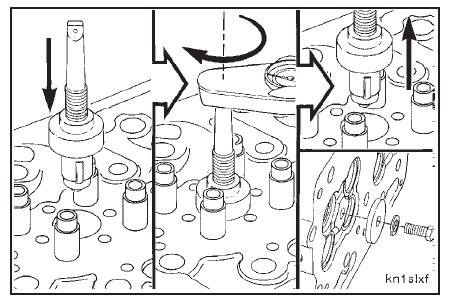
Use an injector sleeve expander, Part No. ST-880, to expand the upper section of the injector sleeve.
Adjust the expander roller edge (1) and the collar (2) to the clearance specified.
Clearance: 40 mm [1.6 inches]

The rollers on the sleeve expander must extend 13 mm to 15 mm [0.5-inch to 0.6-inch] below the top of the in-
jector sleeve. Do not extend the rollers more than 15 mm [0.6-inch] below the top of the sleeve.
Install the expander in the injector sleeve, and turn the mandrel with an inch pound torque wrench.
Torque Value: 8 N•m [75 in-lb]
Remove the expander and the holding tool from the injector sleeve.
Use a pilot, Part No. ST-884-6; a holder, Part No. ST-884-1; and an injector seat cutter, Part No. ST-884-3, to
cut the injector seat.
Install the injector sleeve cutter and the cylinder head in a drill press.
Use a generous amount of cutting oil to lubricate the cutter head during the machining operation to prevent
galling of the injector sleeve.
Carefully machine the injector sleeve until the sealing area is smooth. Remove only the minimum amount of
copper to obtain a smooth sealing area.
Clean the metal particles from the injector sleeve bore.

Caution: Support the cylinder head to prevent damage to the injector tip that protrudes from the combustion
face.
Apply a very light film of blueing compound to the outside diameter of the injector at the injector seat area. Blueing
compound can effectively be applied with your finger or with a brush.

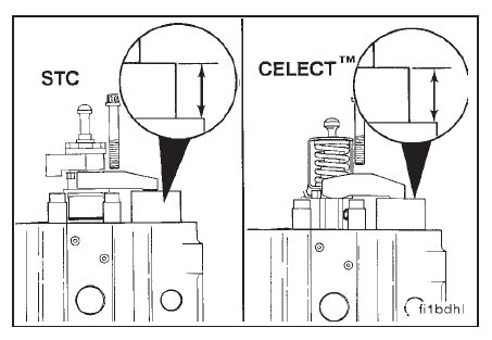
Install the injector in the cylinder head without o-rings.
Place a 1.2-inch thick block under the injector hold down clamp. This represents the rocker housing.
Tighten the injector hold down capscrews.
Torque Value: 54 N•m
[40 ft-lb] STC and CELECTTM
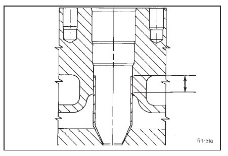
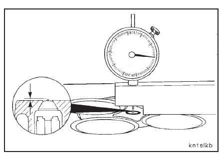
Turn the cylinder head over and use a depth gauge, Part No. 3823495, to measure the injector tip protrusion.
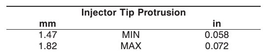
NOTE: If the injector tip protrusion does not meet the specifications given, the injector sleeve must be machined again.
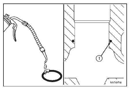
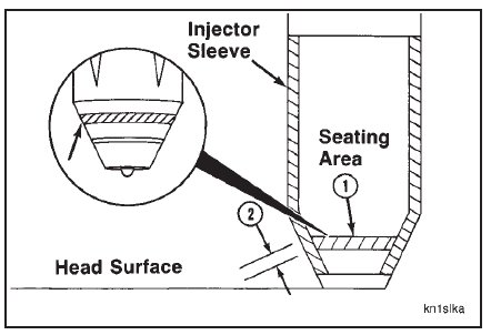
Remove the injectors from the cylinder head, and check the pattern of the blueing compound in the injector sleeve.
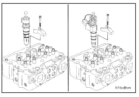
The blueing pattern in the injector seating area (1) must be visible 360 degrees around the seating area.
The injector bore seating width (2) must be a minimum of 1.52 mm [0.060-inch].
NOTE: If the injector protrusion is more than the maximum specified or if the injector sleeve blueing pattern does not
meet the specifications given, the injector sleeve(s) must be replaced. Refer to Cylinder Head – Replacing the Injector Sleeves (02-07).
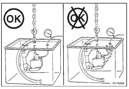
NOTE: Inspect the cylinder head for leaks after the new injector sleeves have been installed. Refer to Cylinder Head
– Pressure Testing (02-08).