NOTE: If the valve guide inside diameter exceeds the maximum worn limit, replace the valve guide before grinding the valve seat.
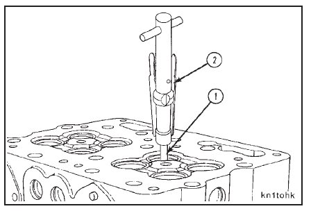
Use a valve seat grinding machine, Part No. ST-685, and valve guide arbor set, Part No. ST-663, when grinding the
valve seat inserts. Install the valve guide arbor (1) in the valve guide with the arbor puller (2).
NOTE: Rotate the arbor to make sure it is correctly installed.
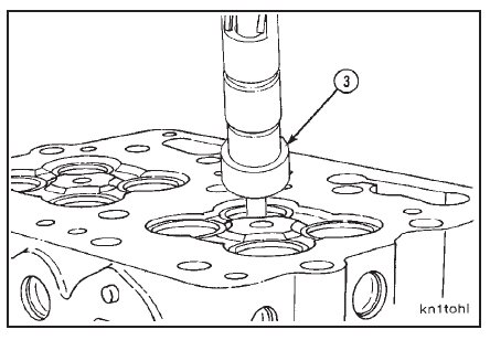
Install a valve seat grinding stone (3), Part No. ST-685-9, on the grinder unit.
NOTE: The grinding stone must be the correct size and have the correct angle (2 1/4-inch diameter X 30-degree grinding angle).
Install the grinder unit on the arbor.
NOTE: The grinding stone (3) must not touch the valve seat insert when the drive unit motor is started.
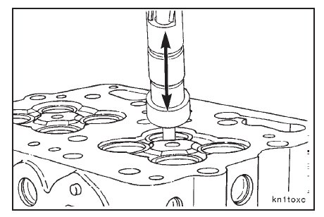
Hold the drive unit in a vertical position, and use an up-and-down movement of 12.7 mm [0.50-inch] travel and
light pressure to grind the insert.
Remove the grinder unit from the arbor.
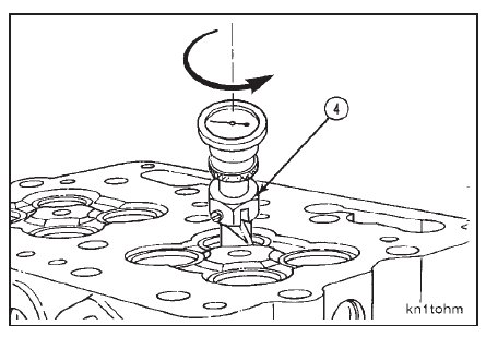
Install eccentrimeter gauge (4), Part No. ST-685-4, on the arbor.
Measure the valve seat to valve guide concentricity.
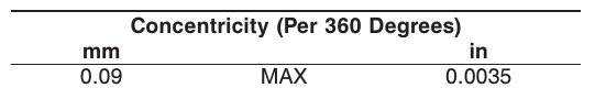
NOTE: If the valve seat concentricity does not meet the specifications, grind the valve seat again. If the specifica-
tions can not be met, replace the valve seat insert. Refer to Cylinder Head – Replacing the Valve Seat Inserts (02-05).
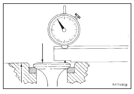
Install reconditioned valves in their respective bores. Hold the valve firmly against the valve seat insert.
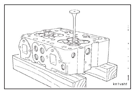
Use a depth gauge, Part No. 3823495, to measure the valve protrusion.
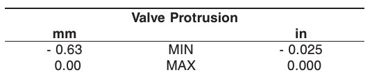
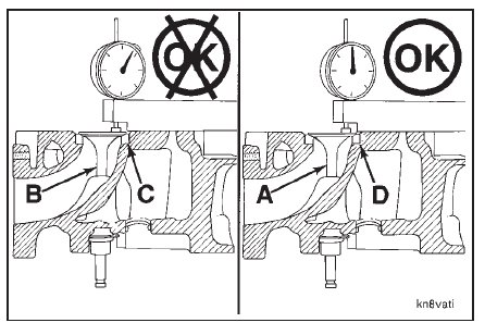
If the valve protrusion is out of limits, replace the old valve (A) with a new valve (B) before replacing the valve seat.
If the protrusion is within limits with the new valve, proceed using the new valve with the old seat.
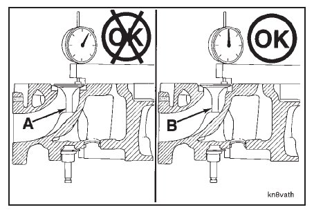
If the valve protrusion is still out of limits, even with the new valve (B), replace valve seat (C) with a new valve seat
(D). After replacing the seat, check the valve protrusion again with the old valve (A) to determine if it can be
reused. If not, proceed using new valve (B).
(A) = Old Valve
(B) = New Valve
(C) = Old Valve Seat
(D) = New Valve Seat
Check the valve seat contact area on the valve face to see if the valve seat contacts the center of the valve face.
Use a pencil or Dykemᮋ to put vertical marks on the face of the valve.
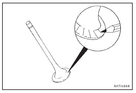
Install the valve in the valve guide. Hold the valve against the valve seat.
Rotate the valve backward and forward three or four times.
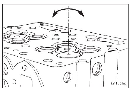
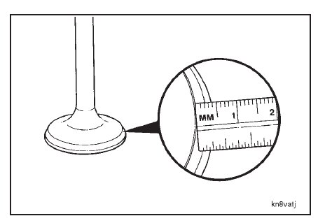
Remove the valve, and measure the valve seat width and the seat contact area as indicated by the broken lines.
The pencil or Dykem marks will be worn away where the valve contacted the seat.
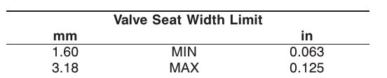
Grind area (A) with a 60-degree stone and area (B) with a 15-degree stone to center the seat on the valve face and
to obtain the valve seat width limits.
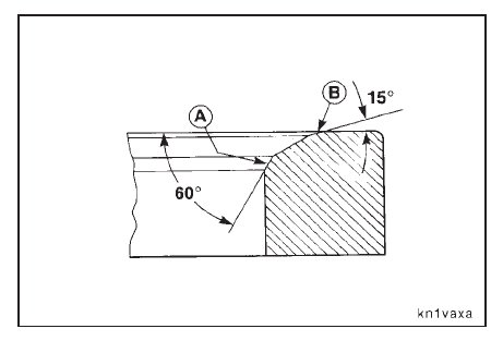
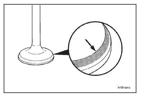
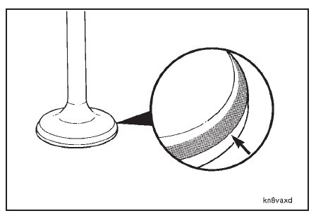
The location of the broken lines on the valve face is the key to determining how much of each angle to grind.
If the broken lines are at the bottom of the valve face, the seat will require more grinding with the 60-degree stone
than with the 15-degree stone.
If the broken lines are at the top of the valve face, the seat will require more grinding with the 15-degree stone than
with the 60-degree stone.
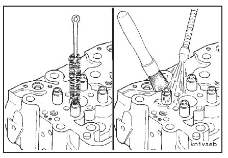
After grinding the valve seats, use a bristle brush to clean the inside diameter of the valve guides.
Use solvent to clean the cylinder head. Dry with compressed air.