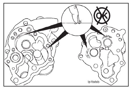
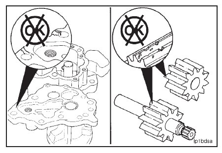
Visually inspect the cover and gear pockets in the body for scratches or other damage.
If the marks on the cover or in the body can be felt with your fingernail, the part must be replaced.
Visually inspect the oil pump body and cover for cracks or damage.
Visually inspect the oil pump gears for worn or damaged teeth.
NOTE: Cracked, worn, or damaged oil pump parts must be replaced.
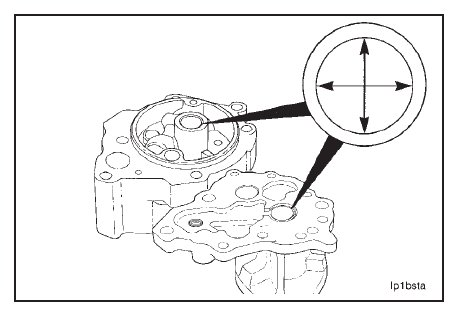
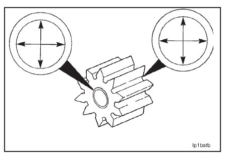
Visually inspect the bushings in the oil pump body and the cover for damage.
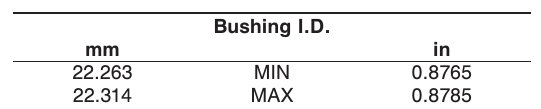
Measure the inside diameter of the bushings in the oil pump body and cover.
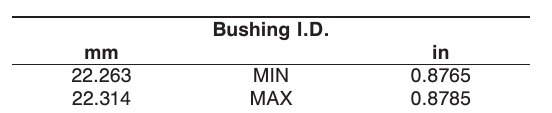
NOTE: If the bushings are worn larger than the maximum given, the bushings must be replaced.
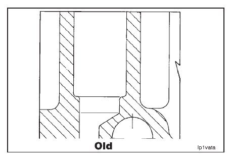
Measure the high oil pressure relief valve seat depth in the oil pump body.
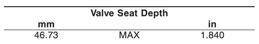
NOTE: If the valve seat depth is greater than the maximum specification given, the oil pump body must be replaced.
Visually inspect the bushings in the driven gear for dam- age.
Measure the inside diameter of the bushings in the oil pump driven gear.
NOTE: If the bushings are worn larger than the maximum given, the bushings must be replaced.
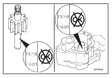
Visually inspect the drive shaft and the driven shaft for damage.
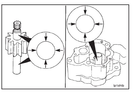
Measure the outside diameter of the drive and the driven shafts in the bushing contact area.
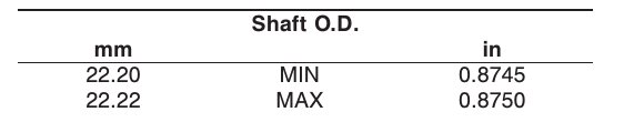
NOTE: Shafts that are damaged or worn smaller than the minimum given must be replaced. Refer to Lubricating Oil
Pump Drive Gear or Shaft – Replacement (07-09).
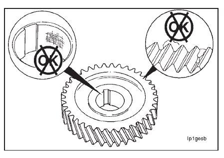
Visually inspect the main drive gear for cracks, chipped, or broken teeth.
Inspect the bore of the gear for scoring or other damage.
Measure the inside diameter of the main drive gear bore.
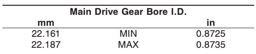
NOTE: If the main drive gear bore is worn beyond the maximum limit, the drive gear must be replaced.
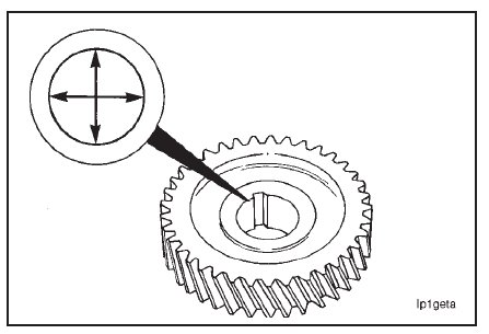
Visually inspect the main oil regulator plunger for scratches or scoring.
NOTE: If scratches are deep enough to be felt with a fingernail, the plunger must be replaced.
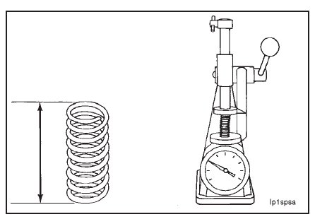
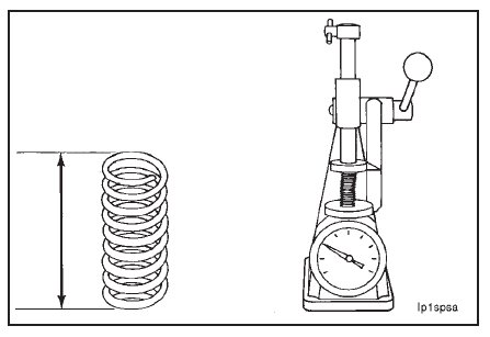
Visually inspect the spring for damaged or broken coils.
Use valve spring tester, Part No. 3375182, to determine if the spring is defective.
NOTE: Compress the spring to a height of 46.23 mm [1.820 inches]. The force required must be:
• Minimum: 98 Newtons [22 lbf]
• Maximum: 116 Newtons [26 lbf]
NOTE: If the force required to compress the spring is not within the specifications given, the spring must be replaced.
Visually inspect the high pressure relief valve retainer plug, the valve disc, the washer, and the valve spring for
damage.
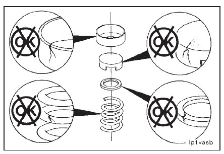
Use valve spring tester, Part No. 3375182, to measure the relief spring tension.
NOTE: Compress the spring to a height of 29.08 mm [1.145 inches]. The force required must be:
• Minimum: 262 Newtons [59 lbf]
• Maximum: 320 Newtons [72 lbf]
NOTE: If the force required to compress the spring is not within the specifications given, the spring must be replaced.