Key-On Engine-Off Tests
Standard Test
The KOEO Standard test is done by the ECM. The technician runs this test, using the EST or the CRUISE
ON and RESUME/ACCEL switches.
During the KOEO Standard test, the ECM does an internal test of its processing components and
memory followed by an Output Circuit Check (OCC).
The OCC evaluates the electrical condition of the circuits, not mechanical or hydraulic performance of the systems. By operating the ECM output circuits and measuring each response, the Standard test detects shorts or opens in the harnesses, actuators, and ECM. If a circuit fails the test, a fault is logged and a DTC is set.
The ECM checks the following circuits:
• Injection Pressure Regulator (IPR)
• Brake shutoff valve (optional)
• Engine Fan (EFAN) (optional)
• Radiator Shutter Enable (RSE) (optional)
When the OCC is done, the DTC window will display DTCs, if there are problems.
Standard Test Using EST
1. Set parking brake to ensure the correct signal from the Electronic System Controller (ESC).
2.Turn the ignition switch to ON. (Do not crank the engine.)

3. Select Diagnostics from the menu bar.
4. Select Key-On Engine-Off tests from the drop down menu.
5. From the KOEO Diagnostics menu, select Standard and Run to start the test.
NOTE: When using the EST to do KOEO or KOER diagnostic tests, Standard test is always selected
and run first. If the ignition switch is not cycled, the Standard test does not have to be run again.

NOTE: Read and be familiar with all steps and time limits in this procedure before starting.
1. Set parking brake to ensure the correct signal from the Electronic System Controller (ESC).
2. Turn the ignition switch to ON. (Do not crank the engine.)
3. Press and release the CRUISE ON and RESUME/ACCEL switches at the same time, twice within 3 seconds of the ignition switch on.
• The ECM will begin the Output Circuit Check (OCC).
When the OCC is done, the ECM will flash the red ENGINE and amber ENGINE lamps to signal the DTCs.
NOTE: There could be as much as a 10 second delay from the time switches are pressed to the time DTCs are flashed.
Injector Test
NOTE: The Injector test can only be done with the EST; MasterDiagnostics® software is required. The
Standard test must be done before doing the Injector test.
The Injector test diagnoses electrical problems in IDM wiring or injectors.
NOTE: Before doing the Injector test, DTCs should be accessed, noted, and cleared. This allows DTCs
found to be displayed as Active DTCs.
During the Injector test, the ECM requests the IDM actuate the injectors in numerical order (1 through 6),
not in firing order. The IDM monitors the electrical circuit for each injector, evaluates the performance
of the injector coils, and checks the operation of the electrical circuit. If an electronic component in the
injector drive circuit fails the expected parameters, the IDM sends a fault to the ECM. The ECM logs the fault,
a DTC is set and sent to the EST.
NOTE: The technician can monitor injector operation by listening to the sound of each injector when
activated by the IDM. During Hard Start and No Start conditions, when oil is very cold and thick, injectors
may be hard to hear.
The DTC window will display DTCs, if there are problems.

1. Select Diagnostics from the menu bar.
2. Select Key-On Engine-Off Tests from the drop down menu.
NOTE: When using the EST to do KOEO or KOER diagnostic tests, Standard test is always selected and run first. If the ignition switch is not cycled, the Standard test does not have to be run again.
3. From the KOEO Diagnostics menu, select Injector and Run to start the test.
NOTE: During the Injector test, injector solenoids should click when actuated. If a series of clicks are
not heard for each injector, one or more injectors are not activating.
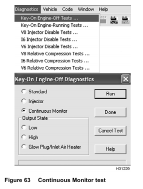
Continuous Monitor Test
NOTE: This test can only be done with the EST; MasterDiagnostics® software is required.
The Continuous Monitor test troubleshoots intermittent connections between the ECM and sensors. The engine can be off or running.
The EST monitors the following circuits:
• Accelerator Position Sensor (APS)
• Barometric Absolute Pressure (BAP)
• Battery Voltage (VBatt)
• Brake Control Pressure (BCP) (optional)
• EGR Valve Position (EGRP)
• Exhaust Back Pressure (EBP)
• Engine Coolant Level (ECL)
• Engine Fuel Pressure (EFP) (optional)
• Engine Oil Pressure (EOP)
• Engine Oil Temperature (EOT)
• Intake Air Temperature (IAT)
• Injection Control Pressure (ICP)
• Manifold Air Temperature (MAT)
• Manifold Absolute Pressure (MAP)

1. Select D_ContinuousMonitor.ssn from the open session file window and select OPEN to open the session.
2. Select Diagnostics from the menu bar.
3. Select Key-On Engine-Off Tests from the drop down menu.
4. From the KOEO Diagnostics menu, select Continuous Monitor and select Run to start the test.
5. Wiggle connectors and wires at all suspected problem locations. If circuit continuity is interrupted, the EST will display DTCs related to the condition.
6. Correct problem causing active DTCs.
7. Clear DTCs.

8. When finished with this test, select Session from menu bar, then Close.
Output State Low Test
NOTE: This test can only be done with the EST; MasterDiagnostics® software is required.
The Output State Low test allows the technician to diagnose the operation of the output signals and actuators.
In the Output State Low test mode, the ECM pulls down the output voltage to the low state. This grounds
the low side driver circuits and actuates the output components controlled by the ECM.
During Output State Low test, the output of the circuit in question can be monitored with a DMM. The DMM
measures a low voltage state as the outputs are toggled. The actual voltage will vary with the circuit tested.
NOTE:
• A Breakout Box or Breakout Harness and a DMM are required to monitor the suspected circuit or actuator.
• DTCs are not set by the ECM during this test.
The following actuators are activated when toggled low during the test:
• Injection Pressure Regulator (IPR) (electrical circuit only)
• Engine Fan (EFAN) relay (optional) (electrical circuit and inspect if clutch is engaged)
• Radiator Shutter Enable (RSE) (optional) (electrical circuit, audible, and visual inspection of shutter position)
• EGR (audible and visual inspection only) continuous monitoring by EGR drive module
• VGT vanes full open (electrical circuit, audible, and visual inspection of actuator arm)

1. Select D_OutputStateTest.ssn from the open session file window.

2. Select Diagnostics from the menu bar.
3. Select Key-On Engine-Off Tests from the drop down menu.
NOTE: When using the EST to do KOEO or KOER diagnostic tests, Standard test is always selected
and run first. If the ignition switch is not cycled, the Standard test does not have to be run again.
4. From the KOEO Diagnostics menu, select Output State Low and Run to start the test.
5. Toggle between the Low and High tests in the Output State Test. Listen and observe actuator control or circuit operation.

6. When finished with this test, select Session from menu bar, then Close.
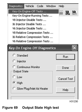
Output State High Test
NOTE: This test can only be done with the EST; MasterDiagnostics® software is required.
The Output State High test allows the technician to diagnose the operation of the output signals and actuators.
In the Output State High test mode, the ECM pulls up the output voltage to the high state. This energizes
the control high side driver circuits and actuates the output components controlled by the ECM.
During this test, the output of the circuit in question is monitored with a DMM. The DMM measures a high
voltage state, as the outputs are toggled. The actual voltage will vary with the circuit tested.
NOTE:
• A Breakout Box or Breakout Harness and a DMM are required to monitor the suspected circuit or actuator.
• DTCs are not set by the ECM during this test.
The following actuators are activated when toggled high during the test:
• VGT vanes full closed (electrical circuit, audible, and visual inspection of actuator arm)
• Brake Shutoff valve (optional) (electrical circuit only)

1. Select D_OutputStateTest.ssn from the open session file window.
2. Select Diagnostics from the menu bar.
3. Select Key-On Engine-Off Tests from the drop down menu.
NOTE: When using the EST to do KOEO or KOER diagnostic tests, Standard test is always selected
and run first. If the ignition switch is not cycled, the Standard test does not have to be run again.
4. From the KOEO Diagnostics menu, select Output State Test High and Run to start the test.
5. Toggle between the Output State Test Low and the Output State Test High. Listen and observe actuator control or circuit operation.

6. When finished with this test, select Session from menu bar, then Close.
Glow Plug/Inlet Air Heater Output State Test
NOTE: This test can only be done with the EST; MasterDiagnostics® software is required.
The Glow Plug/Inlet Air Heater Output State test allows the technician to determine if the Inlet Air Heater System is operating correctly.
The inlet air heater relay operation is activated for 30 seconds. A DMM and current clamp are used to measure the
time the relay is on and the amperage that is drawn for the inlet air heater.

1. Select D_OutputStateTest.ssn from the open session file window.

2. Select Diagnostics from the menu bar.
3. Select Key-On Engine-Off Tests from the drop down menu.
NOTE: When using the EST to do KOEO or KOER diagnostic tests, Standard test is always selected
and run first. If the ignition switch is not cycled, the Standard test does not have to be run again.
4. From the KOEO Diagnostics menu, select Glow Plug/Inlet Air Heater and Run to start the test.
NOTE: This test can only be run twice for each ignition switch cycle. Earlier calibration may not allow the test
to be run, contact International® Technical Services.

5. When finished with this test, select Session from menu bar, then Close.
Key-On Engine-Running Tests
Standard Test
NOTE: The KOER Standard test can only be done with the EST; MasterDiagnostics® software is required.
During the KOER Standard test, the ECM commands the IPR through a step test to determine if the ICP
system is performing as expected. The ECM monitors signal values from the ICP sensor and compares those values to the expected values. When the Standard test is done, the ECM returns the engine to normal operation and transmits DTCs set during the test.
NOTE: Before doing this test, confirm the following conditions:
• Problems causing active DTCs were corrected, and active DTCs were cleared.
• Engine coolant temperature must be at least 70 °C (158 °F).
• Battery voltage must be higher than 10.5 volts.
• No signal from Vehicle Speed Sensor (VSS)
• Transmission in park or neutral

1. With the engine running, select D_KOER_Standard.ssn from the open session file window.

2. Select Diagnostics from the menu bar.
3. Select Key-On Engine-Running Tests from the drop down menu.
4. From the KOER Diagnostics menu, select
Standard and select Run to start the test.
The ECM increases engine idle to a predetermined value and commands the IPR valve to set ICP to rated
speed pressure. If the performance of the ICP system is acceptable, the ECM will control the IPR valve
and reduce the pressure in steps, while continuing to monitor the ICP system.
When the test is done, the ECM restores normal engine operation, and the Diagnostic Trouble Code window will display DTCs, if there are problems.
5. Correct problem causing active DTCs.
6. Clear DTCs.

7. When finished with this test, select Session from menu bar, then Close.
NOTE: When using the EST to do KOEO or KOER diagnostic tests, Standard test is always selected and run first. If the ignition switch is not cycled, the Standard test does not have to be run again.
Continuous Monitor Test
NOTE: This test can only be done with the EST; MasterDiagnostics® software is required.
The Continuous Monitor test troubleshoots intermittent connections at sensors and actuators.
The engine can be off or running.
The EST monitors the following circuits:
• Accelerator Position Sensor (APS)
• Barometric Absolute Pressure (BAP)
• Battery Voltage (VBatt)
• Brake Control Pressure (BCP) (optional)
• EGR Valve Position (EGRP)
• Exhaust Back Pressure (EBP)
• Engine Coolant Level (ECL)
• Engine Fuel Pressure (EFP) (optional)
• Engine Oil Pressure (EOP)
• Engine Oil Temperature (EOT)
• Intake Air Temperature (IAT)
• Injection Control Pressure (ICP)
• Manifold Air Temperature (MAT)
• Manifold Absolute Pressure (MAP)

1. With the engine running, select D_ContinuousMonitor.ssn from the open session file window.

2. Select Diagnostics from the menu bar.
3. Select Key-On Engine-Running Tests from the drop down menu.
4. From the KOER Diagnostics menu, select Continuous Monitor and select Run to start the test.
5. Wiggle connectors and wires at all suspected problem locations. If circuit continuity is interrupted, the EST will display DTCs related to the condition.
6. Correct problem causing active DTCs.
7. Clear DTCs.

8. When finished with this test, select Session from menu bar, then Close.
Air Management Test
NOTE: Before doing this test, Performance Diagnostics tests 1 through 12 should be completed.
Problems with other systems (injectors, fuel supply, etc.) can affect Air Management test results.
NOTE: The Air Management test can only be done with the EST; MasterDiagnostics® software is required. The Standard test must be done before doing the Air Management test.
The Air Management test checks the operation of the Air Management System and the following:
• EVRT® electronically controlled turbocharger – International’s version of a Variable Geometry Turbocharger (VGT)
• Exhaust Gas Recirculation (EGR) valve
During the Air Management test, the ECM commands the VGT control actuator and EGR actuator through
a step test sequence to determine if actuators and the Air Management System are performing as expected. The ECM monitors the feedback signal values from the Exhaust Back Pressure (EBP) sensor and compares those values to the expected values.
If a fault is detected the test will end, engine operation will return to normal, and a DTC will be set.
If there are no faults, the test will be completed and engine operation will return to normal.

1. With the engine running, select D_KOER_AirManagement.ssn from the open session file window and select OPEN to open the session.

2. Select Diagnostics from the menu bar.
3. Select Key-On Engine-Running Tests from the drop down menu.
NOTE: When using the EST to do KOEO or KOER diagnostic tests, Standard test is always selected
and run first. If the ignition switch is not cycled, the Standard test does not have to be run again.
4. From KOER Diagnostics menu, select Air Management and Run to start the test.
5. Correct problem causing active DTCs.
6. Clear DTCs.

7. When finished with this test, select Session from menu bar, then Close.

The ECM commands the EGR valve to close. The ECM then increases engine idle speed to 950 RPM and commands the VGT vanes to fully open. The ECM allows EBP to stabilize. The ECM monitors the EBP pressure and compares this pressure to the expected pressure; pressure is expected to drop. If EBP pressure does not match expected pressure, DTC 345 is set and the test is cancelled.
NOTE: Although commanding the EGR to close, it may be stuck partially open, which would cause EBP values to be lower than expected causing the test to fail during the VGT portion of this test. If this is suspected, the operation of the EGR valve should be visually inspected using the Output State tests.
With the EGR still closed, the ECM commands the VGT vanes to fully close. The ECM allows EBP to stabilize. The ECM monitors the EBP pressure and compares this pressure to the expected pressure; pressure is expected to increase. If EBP pressure does not match expected pressure, DTC 345 is set and the test is cancelled.
With the EGR still closed, the ECM commands the VGT vanes to fully open. The ECM allows EBP to stabilize. The ECM monitors EBP pressure and compares this pressure to the expected pressure; pressure is expected to drop. If EBP pressure does not match expected pressure, DTC 345 is set and the test is cancelled.
If all pressures matched the expected pressures, no DTC is set and the test will continue for EGR.
With the EGR still closed, the ECM increases engine RPM to 1200 rpm and commands the VGT vanes to fully close. The ECM allows EBP to stabilize. The ECM monitors the EBP pressure and compares this pressure to the expected pressure; pressure is expected to increase. If EBP pressure does not match expected pressure, DTC 346 is set and the
test is cancelled.
With the VGT vanes still closed, the ECM commands the EGR to open, and allows EBP to stabilize. The ECM monitors the EBP pressure and compares this pressure to the expected values; pressure is expected to drop. If EBP pressure does not match expected pressure, DTC 346 is set and the test is cancelled.
With the VGT still closed, the ECM then commands the EGR to close, and allows EBP to stabilize. The ECM monitors the EBP pressure and compares this pressure to the expected pressure; pressure is expected to increase. If EBP pressure does not match expected pressure, DTC 346 is set and the engine will return to normal operation.
If all pressures matched the expected pressures, no DTC is set and the engine is returned to normal
operation.
VGT Test
NOTE: The VGT test can only be done with the EST; MasterDiagnostics® software is required. The Standard test must be done before doing the VGT test.
The VGT test is a manual test that allows the technician to set the VGT duty to low, medium, or high and inspect the exhaust system for leaks.
NOTE: Monitor EBP and MAP as VGT duty cycles are changed.

1. With the engine running, select D_KOER_AirManagement.ssn from the open session file window and select OPEN to open the session.

2. Select Diagnostics from the menu bar.
3. Select Key-On Engine-Running Tests from the drop down menu.
NOTE: When using the EST to do KOEO or KOER diagnostic tests, Standard test is always selected
and run first. If the ignition switch is not cycled, the Standard test does not have to be run again.
4. From the KOER Diagnostics menu, select Low Duty Cycle from VGT, and select Run to start test:
Use the suggested toggle sequence below, to check turbocharger operation from one duty cycle to the other.
• Low to medium
• Medium to high
• High to low
• Low to high
If the ECM does not receive a request from the EST, after about 40 seconds, the test will automatically end
and the engine will return to normal operation.

5. When finished with this test, select Session from menu bar, then Close.
Injector Disable Tests
NOTE: The Injector Disable tests can only be done with the EST; MasterDiagnostics® software is required.
The Injector Disable tests allows the technician to shut off injectors to determine if a specific cylinder is
contributing to engine performance. Injectors can be shut off one at a time, alternative cylinders at a time
or alternative cylinders plus one.
Alternate cylinders are every other cylinder in firing order.
Firing order: 1-5-3-6-2-4
When all cylinders are active, the contribution of each cylinder is 17% of its overall effect to maintain governed speed. When three cylinders are shut off, contribution of each remaining cylinder is 33% of its overall effect to maintain governed speed. The technician should monitor fuel rate and engine load.
NOTE: The Relative Compression test should be done after doing the Injector Disable test to distinguish
between an injector or mechanical problem.
NOTE: Before doing the Auto test or Manual test for injector disable, make sure Performance Diagnostics
tests 1 through 10 were completed and the following conditions are maintained:
• Make sure accessories are turned off (for example: engine fan and air conditioning). Items cycled during this test could corrupt the test results.
• Maintain engine idle.
• Keep EOT within a 2 °C (5 °F) range from the beginning to the end of the test. EOT affects injection timing; too much of a change in EOT temperature could corrupt the test results.
NOTE: If any injectors are removed and reinstalled or replaced, test drive vehicle for 20 miles before checking for misfire or rough idle.
Automatic Test
The Automatic test is best used when comparing cylinder to cylinder test data.
NOTE: If MasterDiagnostics® software does not have the Automatic test (auto run feature), see “Injector
Disable – Manual test – Engine Hot” later in this section for procedure to compare cylinder to cylinder.
NOTE: Do KOER Standard test before doing this test.
NOTE: If any injectors are removed and reinstalled or replaced, test drive vehicle for 20 miles before
checking for misfire or rough idle.

1. While engine is running, select D_KOER_IDT_I6.ssn from the open session file window and select OPEN to open
the session.

2. Select Diagnostics from menu bar.
3. Select I6 Injector Disable Tests from drop down menu.
NOTE: The EOT indicator will change from red to green when engine temperature reaches 70 °C (158 °F) or higher.
• If the EOT indicator is red, erroneous comparisons are likely from cylinder to cylinder.
However, when diagnosing a cold misfire, a technician can listen to tone changes from cylinder-to-cylinder.
• When the EOT indicator is green and the engine is at 70 °C (158 °F) or higher, fuel rate and timing are more stable, making comparisons from cylinder to cylinder more accurate. Overall engine operation is more stable.
4. Select Auto Run.
NOTE: While running the engine listen for tone changes from cylinder-to-cylinder.
NOTE: If any injectors are removed and reinstalled or replaced, test drive vehicle for 20 miles before checking for misfire or rough idle.

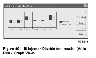
During Auto Run, injectors are shutoff one at a time (1 through 6 numerical sequence). Base line data and
results for each cylinder is displayed in the window (Text View) for I6 Injector Disable test results. Test
data for each cylinder can also be viewed by selecting the (Graph View). When finished the engine will return
to normal operation.

5. When finished with this test, select Session from menu bar, then Close.
Manual Test – Engine Cold
The Manual test is best used when diagnosing each cylinder for cold misfire, considering EOT changes.
The EOT indicator will change from red to green when engine temperature reaches 70 °C (158 °F) or higher.
• If the EOT indicator is red, erroneous comparisons are likely from cylinder to cylinder.
However, when diagnosing a cold misfire, a technician can listen to tone changes from cylinder-to-cylinder.
• When the EOT indicator is green and the engine temperature is 70 °C (158 °F) or higher, fuel rate and timing are more stable, making comparisons from cylinder to cylinder more accurate. Overall engine operation is more stable.
Shut off one injector at a time and listen for changes in exhaust tone.
NOTE: If any injectors are removed and reinstalled or replaced, test drive vehicle for 20 miles before checking for misfire or rough idle.

1. While engine is running, select D_KOER_IDT_I6.ssn from the open session file window and select OPEN to open the session.
2. Select Diagnostics from menu bar.

3. Select I6 Injector Disable Tests from drop down menu.
NOTE: The EOT indicator will change from red to green when engine temperature reaches 70 °C (158 °F) or higher.
• If the EOT indicator is red, erroneous comparisons are likely from cylinder to cylinder.
However, when diagnosing a cold misfire, a technician can listen to tone changes from cylinder-to-cylinder.
• When the EOT indicator is green and the engine temperature is 70 °C (158 °F) or higher, fuel rate and timing are more stable, making comparisons from cylinder to cylinder more accurate. Overall engine operation is more stable.
4. Select cylinder number and select Run. (Injector selected will be disabled and engine noise should change.)
5. Select Normal Operation. Injector will be enabled and engine noise should return to previous state of operation.
6. Repeat steps 4 and 5 for the remaining cylinders.
NOTE: Listen for tone changes from cylinder-to-cylinder.
NOTE: If any injectors are removed and reinstalled or replaced, test drive vehicle for 20 miles before checking for misfire or rough idle.

7. When finished with this test, select Session from menu bar, then Close.
Manual Test – Engine Hot
NOTE: This is an alternate method only. This Manual test should only be used when MasterDiagnostics®
software does not have the Automatic test (auto run feature) and the engine is hot.
The EOT indicator will change from red to green when engine temperature reaches 70 °C (158 °F) or higher.
• If the EOT indicator is red, erroneous comparisons are likely from cylinder to cylinder.
• When the EOT indicator is green and the engine temperature is 70 °C (158 °F) or higher, fuel rate and timing are more stable, making comparisons from cylinder to cylinder more accurate. Overall engine operation is more stable.
Shut off one injector at a time and listen for changes in exhaust tone.
NOTE: Do KOER Standard test before doing the I6 Injector Disable test – Run.

1. While engine is running, select D_KOER_IDT_I6.ssn from the open session file window and select OPEN to open
the session.
2. Select Diagnostics from menu bar.

3. Select I6 Injector Disable Tests from drop down menu.
NOTE: The EOT indicator will change from red to green when engine temperature reaches 70 °C (158 °F) or higher.
• If the EOT indicator is red, erroneous comparisons are likely from cylinder to cylinder.
However, when diagnosing a cold misfire, a technician can listen to tone changes from cylinder-to-cylinder.
• When the EOT indicator is green and the engine temperature is 70 °C (158 °F) or higher, fuel rate and timing are more stable, making comparisons from cylinder to cylinder more accurate. Overall engine operation is more stable.
4. Select Collect Data from I6 Injector Disable Diagnostics window. (Baseline values will be shown.)

5. Record baseline values for EOT, average fuel rate, and average engine load on Diagnostic Form.
NOTE: Listen for tone changes from cylinder-to-cylinder.
6. Select cylinder number and select Run. (Injector selected will be disabled and engine tone should change.)

7. Select Collect Data.
8. Record values for EOT, average fuel rate, and average engine load on Diagnostic Form.
9. Select Done to close Collect Data window.
10. Repeat steps 6 through 9 for the remaining cylinders.
11. Select Normal Operation
12. Subtract the baseline for (average fuel rate) from the (average fuel rate) for each injector and record the difference (deviation) on Diagnostic Form.
13. Add deviations for (average fuel rate) for all injectors and divide by 6. (Round to the nearest tenth – this is the cut off value for fuel rate.)
14. Record cut off value on Diagnostic Form.
15. Subtract the baseline for (average engine load) from the (average engine load) for each injector and record the difference (deviation) on Diagnostic Form.
16. Add deviations for (average engine load) for all injectors and divide by 6. (Round to the nearest tenth – this is the cut off value for engine load.)
17. Record cut off value on Diagnostic Form.
• If deviation values for average fuel rate and average engine load are less than the cut off values for fuel rate and engine load, the injector is suspect for weak cylinder contribution (fuel rate and engine load).
• If only one deviation value is less than a cut off value, do not suspect that cylinder.
• If a suspect cylinder(s) is identified, do Relative Compression test to distinguish between an injector or mechanical problems.
• If the Relative Compression test shows that cylinders are mechanically sound but the Injector Disable test shows that one or more cylinders are bad, replace suspected injector.

18. When finished with this test, select Session from menu bar, then Close.
Relative Compression
NOTE: During this test the IDM shuts off the injectors so no fueling occurs.
NOTE: The Relative Compression test can only be done with the EST; MasterDiagnostics® software is required.
NOTE: This test is used in conjunction with the Injector Disable test to distinguish between an injector problem or a mechanical problem.
The Relative Compression test provides the difference between the fastest and slowest crankshaft speed during the power stroke of each cylinder.
As the engine is cranked, the IDM uses the CMP and CKP sensor signals to measure crankshaft speed,
as piston reaches two points: Top Dead Center (TDC) compression and about 30 degrees after TDC compression.
When the piston approaches TDC, crankshaft speed should be slower because of compression resistance.
As the piston passes TDC, compression resistance dissipates and crankshaft speed increases.
At TDC compression, the cylinder reaches its highest compression and resistance to crankshaft rotation –
Crankshaft speed is the slowest. A cylinder with low compression will have less resistance to crankshaft rotation. Crankshaft speed will be faster than normal.
About 30 degrees after TDC, crankshaft speed should be fastest because compression has dissipated. On a
cylinder that has low compression, crankshaft speed will be close to, or less than crankshaft speed at TDC.
At TDC of each power cylinder, and about 30 degrees past TDC, the IDM collects data for crankshaft speed.
NOTE: If not cranked long enough to collect data, the EST will display 255. 255 represents an erroneous rpm value
The TDC value is subtracted from the value about 30 degrees after TDC and is recorded for each cylinder.
Example
200 rpm (30 degrees after TDC) – 180 rpm (TDC) = 20 rpm
The EZ-Tech® will display a value on the screen for each cylinder.
Example

Compare the compression values of each cylinder with the other cylinder values.
A cylinder with compression lower than the other cylinders indicates a suspect cylinder. Test value of 18 for cylinder one indicates a suspect cylinder.
If a cylinder value is zero or a much lower than other cylinders and this cylinder is a non-contributor (identified in the Injector Disable Test), check for a mechanical problem.
Example

If TDC rpm is greater than rpm 30 degrees after TDC, the EST will display 0.
If the test value for a power cylinder is 0, the cylinder is suspect.
If the test value for a power cylinder is significantly below 15 rpm, the cylinder is suspect.
Test value 5 for cylinder 1 indicates a suspect cylinder.
Test value 0 for cylinder 6 indicates a suspect cylinder.
When the Relative Compression test is done, the EST indicates, stop cranking the engine, and will display test values.
Test data displayed in this test should be compared with data collected from the Injector Disable test.
NOTE: Batteries must be fully charged before doing this test. Use battery charger during this test, if
multiple tests are needed; battery drain can be extensive.
NOTE: Read and be familiar with all steps and time limits in this procedure before starting.

1. Select Diagnostics from the menu bar.
2. Select Relative Compression Tests from the drop down menu.
3. Follow the messages at the bottom of the window.
• Turn the ignition switch to ON.
• Select Run.
• Within 5 seconds of selecting run, crank engine for 15 seconds. Another message will read Stop Cranking within 5 seconds.
Do not turn the ignition switch to OFF. If the ignition switch is turned to OFF, test results will be lost.
NOTE: If test results are identical to previous test results, the current test failed and the previous results were displayed.
4. Interpret results.
• If a Relative Compression test and Injector Disable test identify a suspect cylinder, check
for a mechanical problem.
• If a Relative Compression test does not identify a suspect cylinder, but the Injector Disable test does, replace suspect injector(s).