The function diagram for INJ circuit includes the following:
• Injectors
• Electronic Control Module (ECM)
• Injector Driver Module (IDM)
• Controller Area Network (CAN 1) link
• Camshaft Position Output (CMPO) signal
• Crankshaft Position Output (CKPO) signal
Function
The IDM is used to control the injectors. The IDM receives CMPO and CKPO signals and fueling information via CAN from the ECM. The IDM calculates injection timing and injector actuation time based on the fuel quantity requested for any engine operation condition.
INJ Circuit Operation
When a coil needs to be energized the IDM turns on both the high and low side driver.
High Side Drive Output
The IDM regulates the current at an average of 20 A.
When the current reaches 24 A the IDM shuts off the
high side driver. When the current drops to 16 A the
IDM turns on the high side driver.
Low Side Drive Return
The injector solenoids are grounded through the low side return circuits. The ECM monitors the low side
return circuits. The ECM monitors the low side return signal for diagnostic purposes and utilizes the fly-back
current from the injector solenoids to help charge the drive capacitors internal to the ECM.
Fault Detection / Management
When the engine is running, the IDM can detect individual injector coil open and shorts to ground or
battery. A KOEO Injector Test allows the operator to enable all injector coils when the engine is off to
verify circuit operation. When the IDM detects a fault, Diagnostic Trouble Codes (DTCs) are transmitted
over the CAN 2 line between the ECM and IDM.
The IDM transmits a high and low side drive output to the injectors. The high side output supplies the
injectors with a power supply of 48 V DC at 20 A. The low side output supplies a return circuit to each injector
coil.
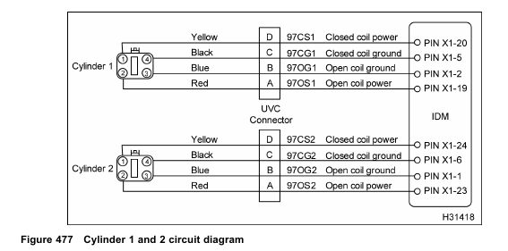
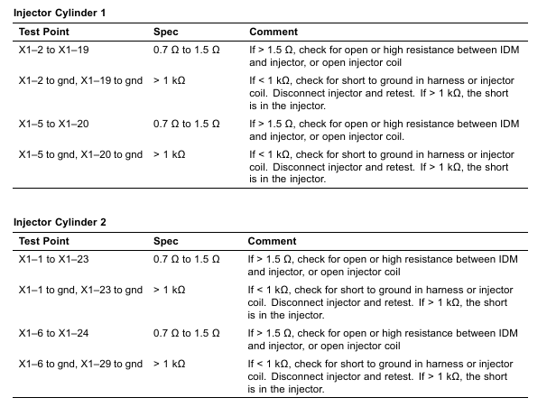
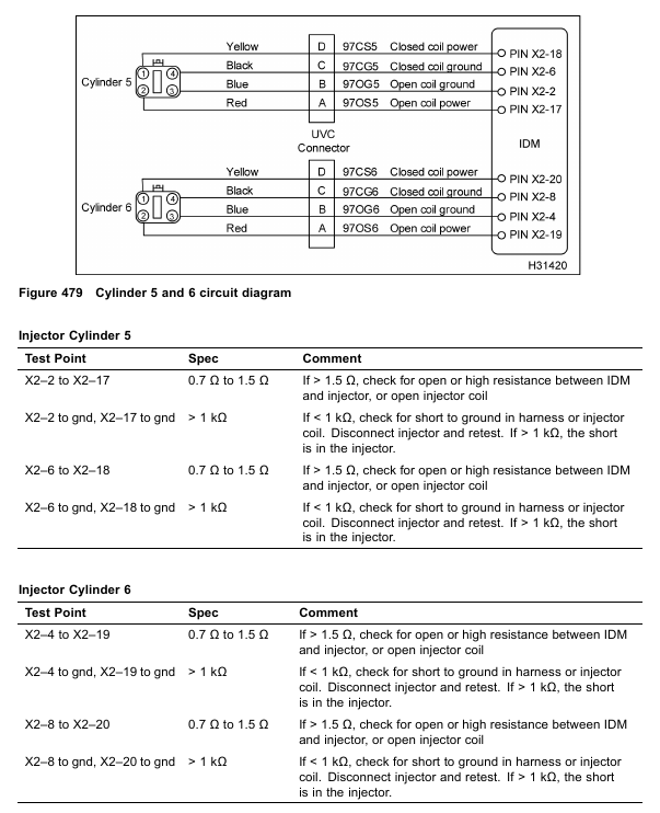
The injectors are under the valve covers. Each injector has a close and open coil. The IDM continuously monitors the amount of time (rising time) taken by each coil to draw 20 A. The time is compared to calibrated values and the IDM determines if a circuit or injector fault exists. Each injector has 6 failure modes and 3 DTCs. A failure can occur on the open or close coil circuit.
When a short to ground condition is detected on an injector (low or high side), the IDM discontinues power to the shorted injector and operates the engine on the remaining cylinders.
INJ Diagnostic Trouble Codes (DTCs)
DTCs are read using the EST or by counting the flashes from the amber and red ENGINE lamp. The last digit in the injector DTC corresponds to the cylinder where a fault has been detected.
DTC 421-426
High side to low side open
• DTC 421–426 is set by the ECM when the rising time is too long for the open or close coil. DTC 421–426 usually indicates a harness or coil is open.
• DTC 421–426 does not set the amber ENGINE lamp.
DTC 431-436
High side shorted to low side
• DTC 431–436 is set by the ECM when the rising time to 20 A is short, but not zero for the open or close coil. DTC 431–436 usually indicates an internally shorted coil.
• DTC 431–436 does not set the amber ENGINE lamp.
DTC 451-456
High side short to ground or VBAT
• DTC 451–456 is set by the ECM when the rising time to 20 A is zero for the open or close coil. DTC 451–458 usually indicates the harness or coil is shorted to ground.
• DTC 451–456 does not set the amber ENGINE lamp.
Tools
• EST with MasterDiagnostics® software
• EZ-Tech® interface cable
• Digital Multimeter (DMM)
• Terminal Test Adapter Kit
INJ Pin-Point Diagnostics
CAUTION: To avoid engine damage, turn the ignition switch to OFF before disconnecting the connector or relay for the IDM. Failure to turn the ignition switch to OFF will cause a voltage spike and damage to electrical components.
Before doing injector diagnostic testing:
1. Turn the ignition switch to OFF.
2. Disconnect IDM connectors (X1 and X2).
All tests are checked at harness end. Pin numbers are marked on all connector mating ends. After checking resistance through injector coils and resistance to chassis ground, if tests are within specification and DTC is active, replace the injector.
NOTE: Only diagnose injectors with active DTCs.