Purpose
To determine if engine systems meet operating specifications to start engine
Monitoring Engine Systems using an EST
Tools
• EST with MasterDiagnostics® software
• EZ-Tech® interface cable
Procedure
NOTE: If an EST is not available, see alternate test procedures following this test.
Batteries must be fully charged before doing the following steps.
1.See “DT 466 Performance Specifications” – Appendix A (page 595) or “DT 570 and HT 570
Performance Specifications” – Appendix B (page 619) for specifications, and record on Diagnostic Form.
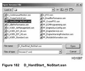
2. Open D_HardStart_NoStart.ssn to monitor engine operation.
3. Turn the ignition switch to ON.
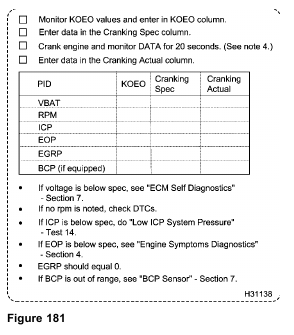
4. Record KOEO readings on Diagnostic Form.
5. Crank engine for 20 seconds and read EST to measure VBAT, RPM, ICP, EOP, EGRP, and BCP.
6. Record readings on Diagnostic Form.
• Battery voltage must be 7 V or more. If voltage to the ECM drops below 7 V, the ECM will not remain powered up.
Note: If the battery volt (VBAT) PID is less than actual battery voltage or the EST is not communicating with the ECM, see Electronic Control Module Power (ECM PWR) in Section 7 (page 381).
• Engine cranking speed must generate the required injection control pressure to operate the fuel injectors and create required compression to ignite the fuel.
• If the EST shows 0 rpm during engine cranking, the ECM may not be receiving a signal from the Crankshaft Position (CKP) sensor or Camshaft Position (CMP) sensor. The ECM will not send the fueling command to the IDM without a correct CKP or CMP signal. See CKP sensor (page 351) and CMP sensor (page 355) in Section 7.
• If the EST indicates low or no injection control pressure, do Test 14 – “Low ICP System Pressure” (page 186).
If the ICP sensor is biased high, see “ICP Sensor” in Section 7 (page 457).
• If oil pressure is low, the ICP system may not be receiving enough oil.
• If EGR valve is open at start-up it can disrupt the air fuel mixture enough to inhibit engine operation.
• BCP values may fluctuate as much as 345 kPa (50 psi). Electromagnetic interference (EMI) or ground shift can cause an insignificant voltage shift that does not indicate a problem. If above 7 MPa (1000 psi), brake actuation may occur. If over 345 kPa (50 psi), ICP operation may be inhibited for fuel injectors.
Possible Causes
Low battery voltage
• Failed batteries
• High-resistance at battery cable connections or in wiring to the ECM
• Failed ECM main power relay
• Blown inline fuse (in battery box) that supplies voltage to the ECM
• Blown fuse in power distribution box
Low cranking rpm
• Electrical system malfunctions, incorrect oil, or long oil change intervals in cold ambienttemperatures
• No rpm indication on the EST while crankingthe engine: Failed CKP sensor, CMP sensor, or circuit to the ECM. Check DTCs after cranking engine for 20 seconds.
Low Injection Control Pressure
• A leak in the high-pressure oil system
• Failed ICP sensor
• Low oil level in the high-pressure oil reservoir
• Failed IPR valve or electronic controls for the regulator
• Failed high-pressure oil pump or pump drive
Low oil pressure
• Failed oil pressure regulator relief valve
• Failed gerotor oil pump or front cover
• Failed pickup tube or gasket
• Internal lube oil pressure leak
EGR valve
• Stuck or inoperative valve
BCP
• Inoperative brake shut-off valve
• Failed BCP sensor
• Failed BCP sensor wiring
• Porosity or sand hole in high-pressure oil rail (injector oil gallery to brake oil gallery)
Monitoring ICP using VC Gasket Breakout Harness
NOTE: Do this procedure, if an EST is not available.
This is an alternate method.
Tools
• VC Gasket Breakout Harness
• Digital Multimeter (DMM)
Procedure
When running the engine in the service bay, make sure the parking brake is set, the transmission is
in neutral, and the wheels are blocked.
1. See “DT 466 Performance Specifications” – Appendix A (page 595) or “DT 570 and HT 570 Performance Specifications” – Appendix B (page 619) and Section 7 for specifications, operational voltages, and values. Record on Diagnostic Form.

2. Disconnect engine harness connector from pass-through connector for ICP sensor.
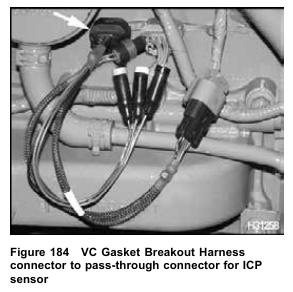
3. Connect VC Gasket Breakout Harness to pass-through connector and engine harness.
When routing DMM leads, do not crimp the leads, run the leads too close to moving parts, or let the leads touch hot engine surfaces.
4. Use DMM to measure injection control pressure (ICP signal voltage) KOEO.
• Connect POS to green (signal circuit) and NEG to black (signal ground).
5. Record KOEO reading on Diagnostic Form.
6. Take another measurement while cranking the engine for 20 seconds.
7. Record reading on Diagnostic Form.
• If ICP voltage is out of specification at KOEO only, see “ICP Sensor” in Section 7 (page 457).
• If ICP voltage is out of specification at engine crank only, do Test 14 – “Low ICP System Pressure” (page 186).
• If ICP voltage is in specification at KOEO and builds to cranking voltage during engine crank, continue to “Monitoring BCP using VC Gasket Breakout Harness” test
Monitoring BCP using VC Gasket Breakout Harness
NOTE: Do this procedure, if an EST is not available.
This is an alternate method.
Tools
• VC Gasket Breakout Harness
• Digital Multimeter (DMM) Procedure
When running the engine in the service bay, make sure the parking brake is set, the transmission is
in neutral, and the wheels are blocked.
NOTE: BCP should be zero, when engine brake is inactive. BCP values may fluctuate as much as 50
psi. Electromagnetic Interference (EMI) or ground shift can cause an insignificant voltage shift that does not indicate a problem. This should be equal to KOEO BCP signal voltage.
1. See “DT 466 Performance Specifications” – Appendix A (page 595) or “DT 570 and HT 570 Performance Specifications” – Appendix B (page 619) and Section 7 for specifications, operational voltages, and values. Record on Diagnostic Form.
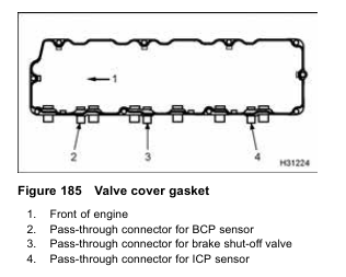
2. Disconnect engine harness connector from the pass-through connector for the BCP sensor.
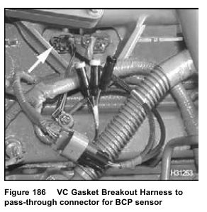
3. Connect VC Gasket Breakout Harness to pass-through connector and engine harness.
When routing DMM leads, do not crimp the leads, run the leads too close to moving parts, or let the leads touch hot engine surfaces.
4. Use DMM to measure brake control pressure (BCP signal voltage) KOEO.
• Connect POS to green (signal circuit) and NEG to black (signal ground).
5. Record KOEO reading on Diagnostic Form.
6. Take another measurement while cranking engine for 20 seconds.
7. Record reading on Diagnostic Form and compare KOEO reading.
• If BCP cranking signal voltage is significantly more than KOEO BCP signal voltage, when engine brake is inactive, diagnose BCP sensor, circuit, and engine brake components.
• If BCP cranking signal voltage is equal to KOEO BCP, signal voltage BCP is not a problem.
Monitoring EOP at EOT Sensor Port
NOTE: Do this procedure, if an EST is not available.
This is an alternate method.
Tool
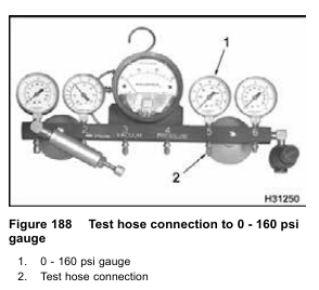
• Gauge bar (0 – 160 psi gauge)
• ICP system test adapter (VT 365)
• Test hose assembly
• Socket or wrench (EOT sensor removal and installation)

1. See “DT 466 Performance Specifications” – Appendix A (page 595) or “DT 570 and HT 570 Performance Specifications” – Appendix B (page 619) and Section 7 for specifications, operational voltages, and values. Record on Diagnostic Form.
2. Make a test hose that will connect the ICP system test adapter to the gauge bar or equivalent gauge.
3. Connect test hose to ICP adapter.
4. Remove the EOT sensor from the front cover. Oil will spill out. Catch oil in container. Quickly install ICP system adapter and test hose assembly. Position hose so oil will not drain out. If oil does not spill out of the EOT port, oil
supply is the problem.
When routing test line, do not crimp the line, run the line too close to moving parts, or let the line touch hot engine surfaces.
5. Connect test hose to gauge bar (0-160 psi gauge) or equivalent gauge.
6. Crank engine for 20 seconds and monitor EOP.
7. Record pressure on Diagnostic Form.
• If oil pressure is below specification, diagnose lube oil pressure system, see Section 4 – “Engine Symptoms Diagnostics” (page 101).
• If oil pressure is at specification, remove test hose and gauge bar. Quickly remove ICP system adapter and test hose assembly. Oil will spill out. Catch oil in container and install EOT sensor. Follow the procedure in Engine Service Manual.
Monitoring Engine Systems using Breakout Box
NOTE: Do this procedure, if an EST is not available.
This is an alternate method.
Tools
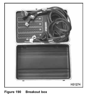
• Breakout Box
• Digital Multimeter (DMM)
Procedure
1. See “DT 466 Performance Specifications” – Appendix A (page 595) or “DT 570 and HT 570 Performance Specifications” – Appendix B (page 619) and Section 7 for specifications, operational voltages, and values. Record on Diagnostic Form.
2. Turn the ignition switch to OFF and ensure all accessories are turned off.
3. Remove X1, X2 and X3, X4 connectors from ECM.
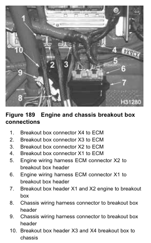
4. Connect breakout box connectors X1, X2 and X3, X4 to ECM.
5. Connect wiring harness connectors to breakout box headers X1, X2 and X3, X4.
6. Connect DMM leads to breakout box.
When routing DMM leads, do not crimp the leads, run the leads too close to moving parts, or let the leads touch hot engine surfaces.
7. Use DMM to measure KOEO values for the following:
• VBAT (DMM set to DC V)
— POS X3–3 to NEG X3–7 (VIGN Pwr)
— POS X4–1 to NEG X3–6 (ECM PWR)
— POS X4–2 to NEG X3–7 (ECM PWR)
• rpm (DMM set to DC mV Hz)
— POS X1–1 to NEG X3–7 (CKP)
• rpm (DMM set to DC mV rpm2)
— POS X1–9 to NEG X3–7 (CMP)
• ICP (DMM set to DC V)
— POS X1–20 to NEG X1–6
• EOP (DMM set to DC V)
— POS X2–7 to NEG X1–6
• BCP (DMM set to DC V)
— POS X2 –11 to NEG X1– 6
8. Record KOEO reading on Diagnostic Form.
9. Take another measurement while cranking engine for 20 seconds.
• If ECM voltage is below specification, see “Electronic Control Module Power (ECM PWR)” in Section 7 (page 381).
• If CKP DCmV Hz is not in specification during crank, see “CKP Sensor” in Section 7 (page 351).
• If CMP DCmV RPM2 is not in specification during crank, see “CMP Sensor” in Section 7 (page 355).
• If EOP is not in specification during crank, see “Low Oil Pressure” in Section 4 (page 128).
• If BCP is not in specification during crank, see “BCP” Sensor” in Section 7 (page 457).
• If all measurements are in specification, continue with the next diagnostic test.
10. Record readings on Diagnostic Form.