Home » ISX11.9 CM2250 - Service Manual » Cummins ISX11.9 CM2250 – Service Manual 016-005   Flywheel

Cummins ISX11.9 CM2250 – Service Manual 016-005   Flywheel

Preparatory Steps

TOC

 WARNING 

Batteries can emit explosive gases. To reduce the possibility of personal injury, always ventilate the compartment before servicing the batteries. To reduce the possibility of arcing, remove the negative (-) battery cable first and attach the negative (-) battery cable last.
 WARNING 

This component weighs 23 kg [50 lb] or more. To reduce the possibility of personal injury, use a hoist or get assistance to lift this component.
  • Disconnect the batteries. Refer to the OEM service manual.
  • If equipped with a wet flywheel housing, drain the oil from the flywheel housing by removing the plug in the bottom of the flywheel housing.
  • Remove the transmission and all related components (if equipped). Refer to the OEM service manual.

SMALL | MEDIUM | LARGE

Initial Check

TOC

Inspect the flywheel ring gear teeth for damage.

If the flywheel ring gear is damaged, make sure to inspect the following possible causes prior to replacing the flywheel.

  • Mechanical
  • Electrical

SMALL | MEDIUM | LARGE


This stepblock is for mechanical checks.

A mechanical issue can typically be identified by seeing damage to the ring gear of the flywheel in three distinct locations for inline 6 cylinder engines (commonly called 120 degree milling). The following could be causes for mechanical issues.

  1. The starting motor spacing may not be correct. Upon installation of the flywheel, make sure to check for proper starting motor spacing. Refer to Procedure 013-020 in Section 13.
  2. Interference between the ring gear land area and the starting motor pinion. The wrong starting motor may be installed. Refer to the OEM specifications.
  3. There may be a defect with the starting motor pinion. Inspect the pinion for nicks and burrs. Replacement of the starting motor may be necessary. Refer to Procedure 013-020 in Section 13.
  4. The ring gear may be improperly installed or damaged. Refer to Procedure 016-008 in Section 16.
  5. The flywheel face runout may be out of specification. See the Measure section of this procedure.
  6. The starting motor pinion-to-flywheel ring gear pitch/teeth match may be incorrect. Refer to the OEM service manual.

SMALL | MEDIUM | LARGE


This stepblock is for electrical checks.

An electrical issue can typically be identified by seeing damage to the ring gear of the flywheel 360 degrees around the circumference of the ring gear (commonly called 360 degree milling). The following could be causes for electrical issues.

  1. The operator is attempting to start the engine while the engine is already operating. Check if a starter lockout feature is available through the OEM (activated with INSITE™ electronic service tool) or the starting motor manufacturer.
  2. The keyswitch is causing intermittent starting motor engagement when the engine is operating. Inspect the keyswitch. Refer to Procedure 013-030 in Section 13.
  3. The orientation of the starter relay is such that the direction of the pull contact is in the direction of the vehicle’s travel. This results in intermittent starting motor engagement when the engine is operating. Relocate the starter relay. Refer to the OEM service manual.
  4. There are intermittent starting motor wiring issues. Refer to the OEM service manual.

SMALL | MEDIUM | LARGE
   

Remove

TOC

 WARNING 

This component weighs 23 kg [50 lb] or more. To reduce the possibility of personal injury, use a hoist or get assistance to lift this component.

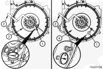
NOTE: Use the barring tool, Part Number 4919092, to hold the flywheel to prevent rotation.

Use flywheel capscrew socket, Part Number 2892191, to remove two capscrews 180 degrees apart.

Install two guide pins. Use guide pin kit, Part Number 3163157.

NOTE: If a clutch is used in the equipment, the threads in the clutch pressure plate mounting capscrew holes can be metric or standard. Be sure to use the correct capscrews.

Determine the capscrew thread design and size, and install two T-handles in the flywheel at points (1 and 2).

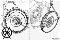
Use a hoist, two t-handles, and a lifting sling. Install the tee-handles. Use flywheel capscrew socket, Part Number 2892191, to remove the remaining ten capscrews and the flywheel.

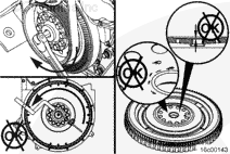
Use a soft-faced mallet to tap the flywheel from the crankshaft, if necessary. Damage to the clutch surface can occur if a hard-faced hammer is used.

SMALL | MEDIUM | LARGE
   

Disassemble

TOC

NOTE: Removal of the pilot bearing is only necessary if it is damaged, or when installing a new or rebuilt clutch.

If equipped, remove the pilot bearing.

Use a mandrel and hammer to remove the pilot bearing.

Use an abrasive pad, Part Number 3823258, or equivalent, to clean the pilot bore.

SMALL | MEDIUM | LARGE
   

Clean and Inspect for Reuse

TOC

 WARNING 

When using a steam cleaner, wear safety glasses or a face shield as well as protective clothing. Hot steam can cause serious personal injury.
 WARNING 

When using solvents, acids or alkaline materials for cleaning, follow the manufacturer’s recommendations for use. Wear goggles and protective clothing to reduce the possibility of personal injury.

Use a wire brush to clean the crankshaft pilot bore.

Use steam or solvent to clean the flywheel.

Dry with compressed air.

SMALL | MEDIUM | LARGE


Inspect for nicks or burrs.

Use Scotch-Brite™ 7448, Part Number 3823258 or equivalent, to remove small nicks and burrs.

SMALL | MEDIUM | LARGE


 WARNING 

Do not use a cracked flywheel. A cracked flywheel can break and cause serious personal injury or property damage.

Inspect the flywheel for cracks.

Use the crack detection kit, Part Number 3375432, to check for cracks in the flywheel. Follow the instructions provided with the kit.

SMALL | MEDIUM | LARGE


Inspect the flywheel ring gear teeth for cracks and chips. There is a long tooth that is used for the timing pick-up. This tooth must not be damaged or broken.

If the ring gear teeth are cracked or broken, the ring gear must be replaced.

SMALL | MEDIUM | LARGE
   

Assemble

TOC

Use a new pilot bearing when installing a new or rebuilt clutch.

Install the pilot bearing with a mandrel and hammer.

The pilot bearing must be installed flush with the pilot bore surface.

SMALL | MEDIUM | LARGE
   

Install

TOC

 CAUTION 

There is a timing dowel pin on the rear face of the crankshaft that aligns the flywheel. If the dowel pin is damaged, broken, or missing, this can cause improper engine performance. The face runout can also be out of specification.

Check to see if the dowel pin is installed in the crankshaft.

Inspect the dowel pin for damage.

If the dowel pin is damaged or broken, replace the dowel pin.

SMALL | MEDIUM | LARGE


 WARNING 

This component weighs 23 kg [50 lb] or more. To reduce the possibility of personal injury, use a hoist or get assistance to lift this component.

Install two M6 x 1.5 guide studs.

Align the flywheel with the dowel pin in the crankshaft.

Install and seat the flywheel onto the crankshaft.

SMALL | MEDIUM | LARGE


 CAUTION 

The flywheel mounting capscrews must be a minimum of SAE Grade 8 with rolled threads. Use identical capscrews as replacements to avoid possible flywheel malfunction, resulting in personal injury or property damage.

Lubricate the threads and underneath the heads of the capscrews with clean 15W-40 oil.

Allow the excess oil to drip off the parts.

Do not lubricate the threads of the crankshaft.

SMALL | MEDIUM | LARGE


Install the ten capscrews.

Remove the “T-handles” and the guide pin.

Install the remaining two capscrews.

Tighten the capscrews in a star pattern.

SMALL | MEDIUM | LARGE


Use flywheel capscrew socket, Part Number 2892191, to tighten the flywheel mounting capscrews in the sequence (star pattern) shown.

Torque Value:

  1. 125 n.m   
    [92 ft-lb]
  2. 251 n.m   
    [185 ft-lb]

SMALL | MEDIUM | LARGE
   

Measure

TOC

Bore Runout


Use dial indicator gauge (1), Part Number 3376050, or equivalent, and dial gauge attachment (2), Part Number ST-1325, to inspect the flywheel bore (3) and face (4) runout.

Install the attachment to the flywheel housing.

Install the gauge on the attachment.

Install the contact tip of the indicator against the inside diameter of the flywheel bore, and set the dial indicator at zero.

SMALL | MEDIUM | LARGE


Rotate the crankshaft one complete revolution (360 degrees). Refer to Procedure 009-035 in Section 9.

Flywheel Total Indicator Reading

mm in
0.127 MAX 0.0050

SMALL | MEDIUM | LARGE


 WARNING 

This component weighs 23 kg [50 lb] or more. To reduce the possibility of personal injury, use a hoist or get assistance to lift the component.

If the total indicator reading is greater than the specification:

Remove the flywheel.

SMALL | MEDIUM | LARGE


Inspect the flywheel mounting surface for dirt or damage.

SMALL | MEDIUM | LARGE


 CAUTION 

There is a timing dowel pin on the rear face of the crankshaft that aligns the flywheel. If the dowel pin is damaged, broken, or omitted, improper engine performance and/or face runout will be out of specfication.

Check to see if the dowel pin in the crankshaft is installed.

Inspect the dowel pin for damage. If the dowel pin is damaged or broken, replace the dowel pin.

Inspect the crankshaft for dirt or damage.

SMALL | MEDIUM | LARGE


 WARNING 

This component weighs 23 kg [50 lb] or more. To reduce the possibility of personal injury, use a hoist or get assistance to lift this component.

Install the flywheel, and inspect the bore runout again.

SMALL | MEDIUM | LARGE


 WARNING 

This component weighs 23 kg [50 lb] or more. To reduce the possibility of personal injury, use a hoist or get assistance to lift this component.

Replace the flywheel if the runout does not meet specifications.

SMALL | MEDIUM | LARGE
   

Face Runout


Install the contact tip of the indicator against the flywheel face as close to the outside diameter as possible to inspect the face runout.

When locating the contact tip, see the Flywheel Face Runout Total Indicator Reading Table later in this procedure. Locate the contact tip so that it corresponds with a radius listed in the table, but is still as close to the outside diameter of the flywheel as possible, to inspect the flywheel face (1) runout.

Push the flywheel forward to remove the crankshaft end clearance.

Adjust the dial on the indicator until the needle points to zero.

SMALL | MEDIUM | LARGE


Rotate the crankshaft one complete revolution. Measure and record the flywheel runout at four equal points on the flywheel. Refer to Procedure 009-035 in Section 9.

The flywheel must be pushed toward the front of the engine to remove the crankshaft end clearance each time a point is measured.

Determine the total indicator reading (TIR).

TIR is determined by calculating the difference between the highest and lowest measurement from the four locations measured.

SMALL | MEDIUM | LARGE


Flywheel Face Runout Total Indicator Reading
Flywheel Radius (A)
Maximum Total Indicator Reading of Flywheel Face
mm
in
mm
in
203
8
0.203
0.008
254
10
0.254
0.010
305
12
0.305
0.012
356
14
0.356
0.014
406
16
0.406
0.016
 
SMALL | MEDIUM | LARGE


If the flywheel face runout is not within specifications, remove the flywheel.

First check for nicks, burrs, or foreign material between the flywheel mounting surface and the crankshaft flange.

Replace the flywheel if the runout is not within specification.

SMALL | MEDIUM | LARGE
   

Finishing Steps

TOC

 WARNING 

This component weighs 23 kg [50 lb] or more. To reduce the possibility of personal injury, use a hoist or get assistance to lift this component.
  • Install the transmission and all related components (if equipped). Refer to the OEM service manual.
  • If equipped with a wet flywheel housing, fill the flywheel housing with oil. Refer to the OEM service manual.
  • Align the universal joints on each end of the driveshaft to prevent vibration.
  • Operate the engine and check for proper operation.

SMALL | MEDIUM | LARGE
Last Modified:  06-Jan-2011