[1] – Install display module with eight screws (A).
[2] – Connect wiring harness connectors to turn signal switch (B), and light switch (C) on left side of panel.

[3] – Connect wiring harness connectors to PTO switch (D) and key switch (E) on right side of panel.

[4] –
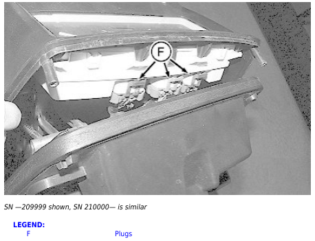
→NOTE:
SN 210000— has two connectors at top and one at bottom.
Connects plugs (F) to display module.
[5] – Slide park brake rod (G) into park brake handle (H).

[6] – Fit control panel to cowl and firewall and install screws (I).

[7] – Install one screw (J) on each side of cowl.
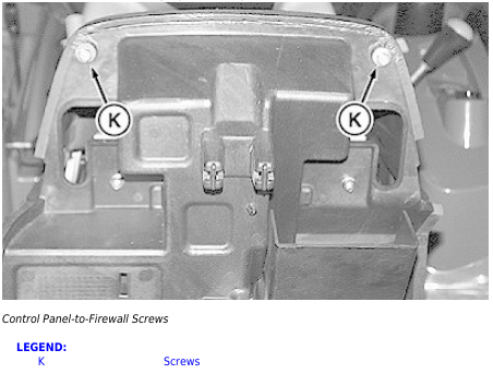
[8] – Install screws (K) securing top of control panel to firewall.
[9] – Install steering wheel and tighten steering wheel nut to specification. Install steering wheel cover. (See Remove and Install Steering Wheel in Section 60, Group 5.)