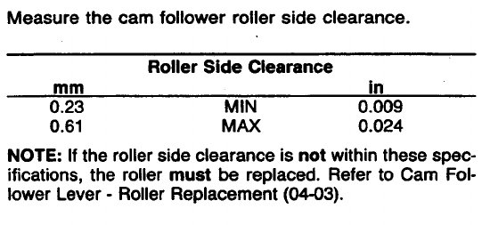
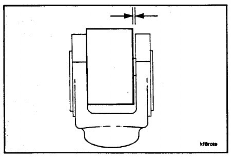
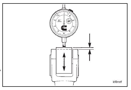
Use a dial indicator to measure the cam follower to roller pin clearance.
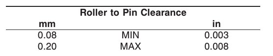
NOTE: If the roller to pin clearance is not within these specifications, the roller and the pin must be replaced. Refer to
Cam Follower Lever – Roller Replacement (04-03).
Measure the cam follower lever shaft bore inside diameter.
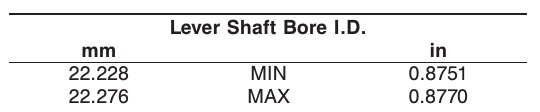
NOTE: Valve and injector levers without bushings were introduced on January 1, 1987. If the shaft bore is worn beyond the maximum specification, the lever must be replaced.
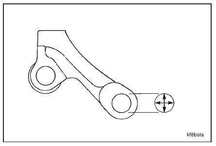
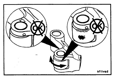
Visually inspect the sockets for excessive wear or damage.
A good even seating pattern must be seen when inspecting the cam follower socket.
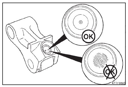
When parallel grooves and scratches are observed or the contact area extends into the oil hole chamfer of the
socket, the worn socket must be replaced.
NOTE: If excessive wear or damage is found in the sockets, the sockets must be replaced. Refer to Cam Follower Socket – Replacement (04-04).
Do not use push rods with worn balls in cam followers with new sockets. Refer to Push Rod – Cleaning and Inspection
for Reuse (04-05).
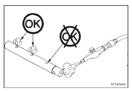
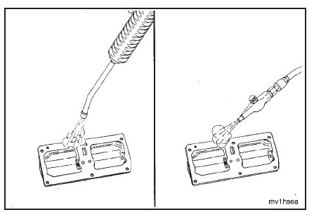
Use clean 15W-40 oil to check the oil flow through the cam followers.
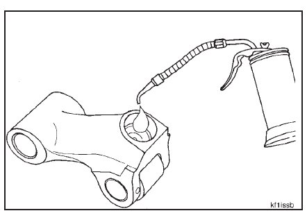
Clean the cam follower shafts with solvent. Dry with com pressed air.
Make sure the oil drillings are not restricted or plugged.
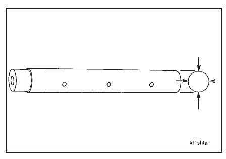
Visually inspect the cam follower shafts for scoring or damage.
Visually inspect the locking screw holes in each shaft.
The grooves must be clean and not damaged.

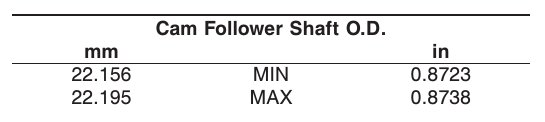
Measure the cam follower shaft outside diameter.
Steam clean the cam follower housings. Dry with compressed air.
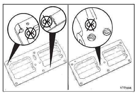
Visually inspect the cam follower housings for cracks or damage.
Visually inspect the locking screw holes for damaged or distorted threads.
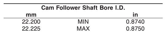
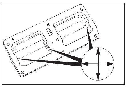
Measure the cam follower shaft bore inside diameter.