Use a connecting rod checking fixture, Part No. ST-561, and a connecting rod mandrel set, Part No. 3823785, to
inspect the bend and the twist of the rods.
Calibrate the checking fixture with a new rod that has been measured for correct center to center length, 304.75
mm to 304.80 mm [11.998 inches to 12.000 inches].
NOTE: Assemble the connecting rod cap to the rod as described in Connecting Rods – Inspection.
Install the piston pin mandrel from the connecting rod mandrel set, Part No. 3823785, into the piston pin bore.
NOTE: Use a mandrel, Part No. 3823787, if the piston pin bushing has been removed or the mandrel, Part No.
3823788, if the bushing is still in place.
Install the mandrel, Part No. 3823786, into the crankshaft bore and expand the mandrel.
NOTE: Make sure the pin on the mandrel is pointed down and locked in position in the center of the connecting rod.

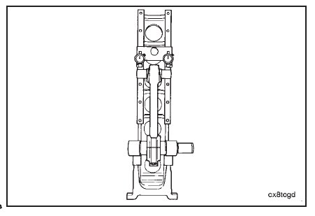
Install the connecting rod into the fixture.
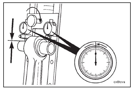
Move the dial holder to position the contact points of the indicators on the mandrel in the piston pin bore.
Tighten the bracket to hold the indicators in position.
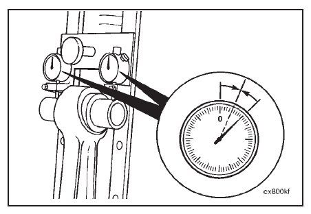
Set the dial indicators to read ‘‘0.’’
Remove the connecting rod from the fixture.
Turn the rod 180 degrees horizontally, and install the rod into the fixture again.
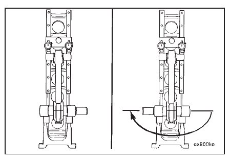
Check the dial indicators for the ‘‘0’’ position again.
If the dial indicators show any change from ‘‘0,’’ adjust the dials to half the indicated reading.
The fixture is now calibrated to allow the connecting rod to be installed into the fixture in either direction, and the
dials will indicate an equal deflection on either side of ‘‘0.’’