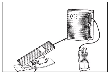
When testing a CELECTTM engine on an engine dynamometer, it is necessary to attach a throttle input control,
and a 12 volt power supply to the ECM.
A CompulinkTM must also be used to bypass certain features and programmed parameters associated with the
CELECTTM ECM while the engine run-in or performance test is in process.
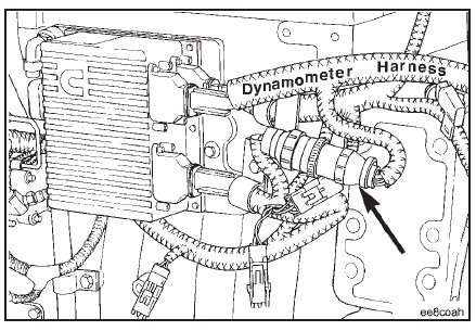
The engine dynamometer OEM harness for both the N14 and L10 engines are the same. The CELECTTM dyna-
mometer test OEM wiring harness, Service Tool Part No. 3823948, is available through Cummins. The harness is
supplied with all necessary connections and switches.
Items not supplied are the remote throttle actuator and the 12 volt battery.
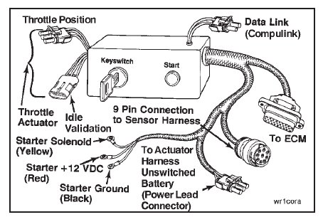
Connect the dynamometer test OEM wiring harness AMP connector to the ECM. Tighten the connector capscrews
to the ECM.
Torque Value: 2.0 N•m [18 in-lb]

Connect the dynamometer test OEM wiring harness 3-pin connector to the actuator harness power connector
(shroud).

Connect the dynamometer test OEM wiring harness 9-pin connector to the sensor harness 9-pin connector.
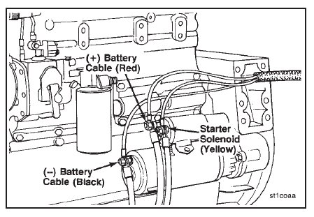
Connect the battery power to the starting motor.
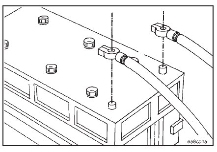
Connect the dynamometer test OEM wiring harness starting motor solenoid lead (yellow) to the starting motor
solenoid. Connect the ground lead (black) to the starting motor or battery negative or ground side. Connect the
+12 volt DC power lead (red) to either the starting motor or battery positive (+12 volt DC) side.
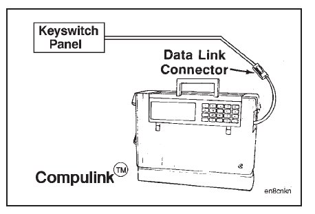
To control throttle input and engine speed, connect the auto/manual throttle control, Service Tool Part No.
3823828, to the throttle control leads at the keyswitch panel on the dynamometer test OEM wiring harness.
Place the ‘‘Auto-Manual’’ switch in the ‘‘Manual’’ position to enable use of the ‘‘Min-Max RPM Adjust’’ control.
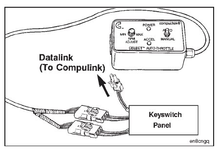
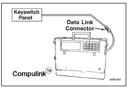
Connect the keyswitch panel datalink cable to the CompulinkTM.
Depress the ‘‘POWER ON’’ button on the CompulinkTM.
If the ‘‘Progressive Shift Feature’’ is turned ‘‘ON’’, it must be turned ‘‘OFF’’ during the engine test to allow the
engine to accelerate through its RPM range.
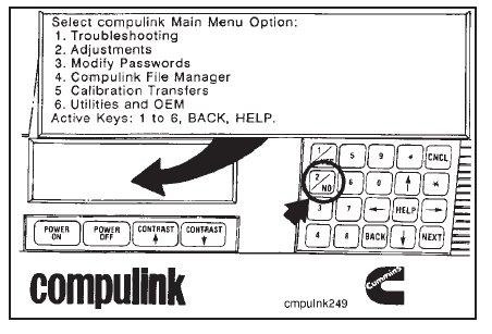
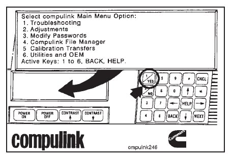
Select the ‘‘Adjustments’’ option from the main menu screen by depressing the number ‘‘2’’ on the CompulinkTM
keypad.
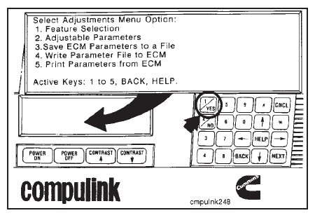
Select the ‘‘Feature Selection’’ from the menu options by depressing the number ‘‘1’’ on the keypad.
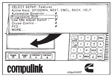
The next screen will show if the ‘‘Progressive Shift Feature’’ is turned ‘‘ON’’ or ‘‘OFF’’.
Check the ‘‘Progressive Shift Feature’’. If ‘‘Y’’ is displayed, depress the number ‘‘2’’ key on the keypad to
display ‘‘N’’ and turn ‘‘OFF’’ the ‘‘Progressive Shift’’.
NOTE: Turn the ‘‘Progressive Shift Feature’’ back ‘‘ON’’ when the test is completed.
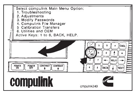
Depress the active key to cancel or back up to the screen showing the ‘‘Main Menu Option’’.
The ECM is equipped with a tamperproof system that limits engine speed when the vehicle speed signal is lost.
This parameter must be bypassed with the CompulinkTM in the Compuchekᮋ mode or if the CompulinkTM is needed
to monitor engine data, the adjustable parameters must be adjusted outside the engine operating range.
To save, adjust, and write parameters to and from the ECM, refer to the CELECTTM CompulinkTM Cartridge Manual, Bulletin No. 3810472.
NOTE: Parameters must be returned to their original value when the test or run-in is completed.
If the parameter is to be bypassed with the CompulinkTM, refer to the following instructions.
Select ‘‘Troubleshooting’’, key (1), from the ‘‘Main Menu Option’’ screen.
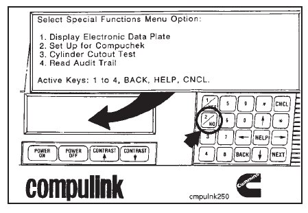
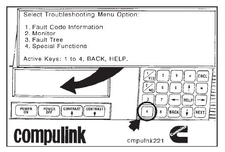
Select ‘‘Special Functions’’, key (4), from the ‘‘Troubleshooting Menu’’.
Select ‘‘Set Up for Compuchek’’ from the ‘‘Special Functions Menu’’. The CompulinkTM must be left in this mode
throughout the test.
The setup is now completed, and the auto/manual throttle control can be used to control engine speed.
NOTE: The throttle control must be used in the manual position.
Use the active keys to cancel or back up the CompulinkTM when the test is complete.