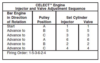
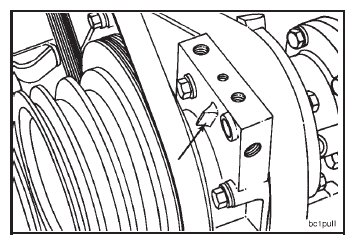
The valve set marks are located on the accessory drive pulley. The marks align with a pointer on the gear cover.
Use the accessory drive shaft to rotate the crankshaft.
The crankshaft rotation is clockwise when viewed from the front of the engine.
The cylinders are numbered from the front end of the engine.
The engine firing order is 1-5-3-6-2-4.

All overhead (valve and injector) adjustments must be made when the engine is cold (any stabilized coolant
temperature at 60°C [140°F] or below).

Each cylinder has three rocker levers. The rocker lever nearest to the center of the housing is the intake lever.
• The exhaust rocker lever (1).
• The injector rocker lever (2).
• The intake rocker lever (3).
The two levers closest to the center of each rocker housing are the intake rocker levers. The two levers closest to
the ends of the rocker housing are the exhaust levers.

The valves and the injectors on the same cylinder are adjusted at the same index mark on the accessory drive
pulley.
One pair of valves and one injector are adjusted at each pulley index mark before rotating the accessory drive to
the next index mark.
Two crankshaft revolutions are required to adjust all the valves and the injectors.
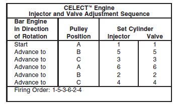
Rotate the accessory drive in the direction of engine rotation. The accessory drive will rotate clockwise on a
right hand engine, when looking at the front of the engine.
Align the ‘‘A’’ mark on the accessory drive pulley with the pointer on the gear cover.

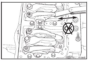
Check the valve rocker levers on cylinder No. 1 to see if both valves are closed.
NOTE: Both valves are closed when both rocker levers are loose and can be moved from side to side. If both valves are not closed, rotate the accessory drive one complete revolution; and align the ‘‘A’’ mark with the pointer again.
If the valve rocker lever adjusting screws have been loosened and not yet adjusted, watch the valve push tubes
as the engine rolls upon the ‘‘A’’ mark. Both valve push tubes will have moved to the downward (valve closed)
position if the engine is on the correct stroke.

Loosen the injector adjusting screw lock nut on cylinder No. 1. Bottom the injector plunger by tightening and
loosening the adjusting screw 2.8 N•m [25 in-lb] three or four times to remove the fuel.
NOTE: Do not bottom the plunger any tighter than 2.8 N•m [25 in-lb] when removing the excess fuel.
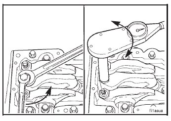
Tighten the adjusting screw on the injector rocker lever.
Torque Value: 2.8 N•m [25 in-lb]

Caution: After preloading the CELECT™ injector to 2.8 N•m [25 in-lb], make sure to back out the adjusting
screw two flats (120 degrees) or damage to the injector will result.
Back out the adjusting screw on the injector rocker lever two flats (120 degrees).
NOTE: Two flats will provide 0.63mm[0.025 inch] lash. The specification is 0.50 to 0.74 mm [0.020 to 0.029 inch] lash.

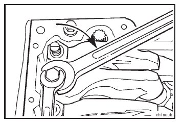
Hold the adjusting screw and tighten the lock nut.
Torque Value: 68 N•m [50 ft-lb]
After setting the injector on a given cylinder, set the valves on the same cylinder.
With the ‘‘A’’ set mark aligned with the pointer on the gear cover and both valves closed on cylinder No. 1, loosen
the lock nuts on the intake and the exhaust valve adjusting screws.

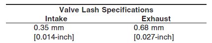
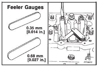
Select a feeler gauge for the correct valve lash specification.
Insert the feeler gauge between the top of the crosshead and the rocker lever pad.
Two different methods for establishing valve lash clearance are described below. Either method can be used;
however, the torque wrench method has proven to be the most consistent.
• Torque Wrench Method: Use the inch pound torque wrench, part No. 3376592, (normally used to set
preload on STC injectors), and tighten the adjusting screw.
Torque Value: 0.6 to 0.7 N•m [5 to 6 in-lb]
• Feel Method: Tighten the adjusting screw until a slight drag is felt on the feeler gauge.
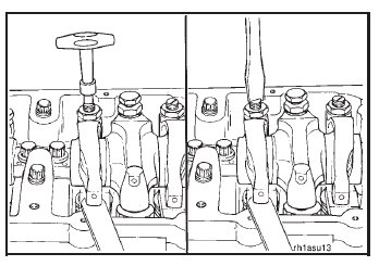
Hold the adjusting screw in this position. The adjusting screw must not turn when the lock nut is tightened.
Torque Values:
With torque wrench adapter, Part No. ST-669 54 N•m [40 ft-lb]
Without adapter 68 N•m [50 ft-lb]

After tightening the lock nut to the correct torque value, check to make sure the feeler gauge will slide backward
and forward between the crosshead and the rocker lever with only a slight drag.
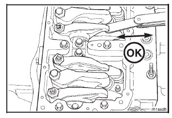
If using the feel method, attempt to insert a feeler gauge that is 0.03 mm [0.001-inch] thicker between the crosshead
and the rocker lever pad. The valve lash is not correct when a thicker feeler gauge will fit.
After adjusting the injector on cylinder No. 1 and the valves on cylinder No. 1, rotate the accessory drive; and
align the next valve set mark with the pointer.
Adjust the appropriate injector and valves following the Injector and Valve Adjustment Sequence Chart.
Repeat the process to adjust all injectors and valves correctly.
Install the engine brakes again, if equipped. Refer to Engine Brake – Installation in this Section.