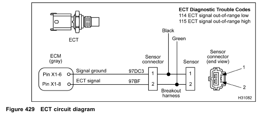
The ECT sensor is supplied with a 5 V reference voltage at Pin 2 from ECM Pin X1–8. The sensor is grounded at Pin 1 through the signal ground at the ECM Pin X1–6. As the coolant temperature increases or decreases, the sensor changes resistance and provides the coolant temperature signal voltage at the ECM. The signal voltage is monitored by the ECM to determine the temperature of the coolant.
Fault Detection / Management
The ECM continuously monitors the signal of the ECT sensor to determine if the signal is within an expected range. If the ECM detects an out of range high or low, the ECM will ignore the ECT signal and assume an engine coolant temperature of -20 °C (-4 °F) for starting and 82 °C (180 °F) for engine running conditions. When this occurs, the EWPS, CAP, IST, cold idle advance, and coolant temperature compensation features are disabled.
ECT Diagnostic Trouble Codes (DTCs)
DTCs are read using the EST or by counting the flashes from the amber and red ENGINE lamp.
DTC 114
ECT signal out-of-range low
• DTC 114 set by the ECM when the ECT signal is less than 0.127 V for more than 0.35 second.
• DTC 114 can set due to a short to ground in the signal circuit or a failed ECT sensor.
• When DTC 114 is active the amber ENGINE lamp is illuminated.
DTC 115
ECT signal out-of-range high
• DTC 115 set by the ECM when the ECT signal is more than 4.6 V for more than 0.35 second.
• DTC 115 can set due to an open signal or ground circuit, a short to a voltage source, or a failed ECT sensor.
• When DTC 115 is active the amber ENGINE lamp is illuminated.
Tools
• EST with MasterDiagnostics® software
• EZ-Tech® interface cable
• Digital Multimeter (DMM)
• 3-Banana Plug Harness
• 500 Ohm Resistor Harness
• Breakout Box
• Breakout Harness
• Terminal Test Adapter Kit