
The EOP sensor is supplied with a 5 V reference voltage at Pin 2 from ECM Pin X1–14. The EOP sensor is grounded at Pin 1 from ECM Pin X1–6. The EOP sensor returns a variable voltage signal from Pin 3 to ECM Pin X2–7.
Fault Detection / Management
When the EOP signal voltage is detected out of range high or low, the ECM will cause the engine to ignore the EOP signal and disable the EWPS.
EOP Diagnostic Trouble Codes (DTCs)
DTCs are read using the EST or by counting the flashes from the amber and red ENGINE lamp.
DTC 211
EOP signal out-of-range low
• DTC 211 is set by the ECM when the EOP signal is less than 0.039 V for more than 0.35 second.
• DTC 211 can be set due to an open or short to ground on the signal circuit, a failed ICP sensor or an open VREF circuit or VREF short to ground.
• When DTC 211 is active the amber ENGINE lamp is illuminated.
DTC 212
EOP signal out-of-range high
• DTC 212 is set by the ECM when the EOP signal is greater than 4.9 V for more than 0.35 second.
• DTC 212 can be set due to signal circuit short to VREF or B+, or a failed EOP sensor.
• When DTC 212 is active the amber ENGINE lamp is illuminated.
DTC 225
EOP sensor signal in-range fault
• DTC 225 is set by the ECM when the EOP signal voltage is greater than 207 kPa (30 psi)
for 8 seconds or more with the ignition key-on engine-off.
• DTC 225 can be set due to an open signal ground, VREF shorted to voltage source above 5.5 V, biased circuit, failed EOP sensor.
• When DTC 225 is active the amber ENGINE lamp is illuminated.
Tools
• EST with MasterDiagnostics® software
• EZ-Tech® interface cable
• Digital Multimeter (DMM)
• 3-Banana Plug Harness
• 500 Ohm Resistor Harness
• Breakout Box
• Breakout Harness
• Terminal Test Adapter Kit
EOP Operational Diagnostics
1. Using EST, open the D_ContinuousMonitor.ssn.
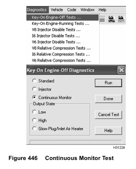
2. To monitor signal voltage, run KOEO Continuous Monitor Test. For help, see “Continuous Monitor Test” in Section 3 (page 68).
3. Monitor EOP signal voltage. Verify an active DTC for the EOP circuit.
4. If code is active, do step 6 and 7 to check circuit for the EOP sensor using the following table.
• Circuit Checks for EOP Sensor
5. If code is inactive, wiggle connectors and wires at all suspected problem locations. If circuit continuity is interrupted, the EST will display DTCs related to the condition.
6. Disconnect engine harness from pressure sensor.
NOTE: Inspect connectors for damaged pins, corrosion, or loose pins. Repair if necessary.
7. Connect Pressure Sensor Breakout Harness to engine harness only.

