Purpose
To determine the cause of low injection control pressure that prevents engine starting
Tools
• EST with MasterDiagnostics® software
• EZ-Tech® interface cable
• Digital Multimeter (DMM)
• Actuator Breakout Harness
• Jumper harness (from Terminal Test Kit)
• Pressure Sensor Breakout Harness
• Socket or wrench (EOT sensor)
• Compressed air source 689 kPa (100 psi)
• Spare VT 365 ICP sensor (Part No. -1845274C92 or equivalent)
• Spare high-pressure hose (Part No.-1842571C91 or equivalent)
NOTE: The mechanic is expected to keep the spare ICP sensor and high-pressure hose for future diagnostics. Expense the spare ICP sensor and high-pressure hose as essential tools and keep it with other diagnostic tools. Warranty will not cover the cost of the spare ICP sensor and high-pressure hose.
Possible Causes
• ICP system leakage
• Failed ICP sensor circuit
• Failed ICP sensor
• Failed IPR wiring (power and control)
• Failed IPR valve
• Low or no lube oil pressure
• Inoperative high-pressure oil pump
• Failed BCP sensor circuit
• Failed BCP sensor
• Inoperative brake shut-off valve of Diamond Logic® engine brake
• BCP system leakage
• If ECM detects low boost pressure, an incorrect feedback signal from APS or the ICP sensor, the ECM commands the IPR valve to reduce ICP.
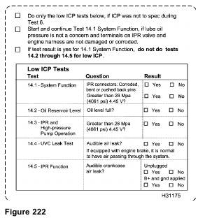
14.1 – System Function
Start Test 14.1 System Function – continue Low ICP System Pressure diagnostics, if no concerns are found with the following:
• Lube oil pressure system has the ability to build engine oil pressure while the engine is cranking.
• Inspect Injection Pressure regulator (IPR) valve and engine wiring harness connector for corrosion.

Procedure
1. Disconnect engine wiring harness connector from IPR valve and inspect engine harness terminals and IPR valve for corrosion, bent pins, or pins pushed back.
• If the harness connector or the IPR valve is corroded, replace the harness connector and IPR valve. Retest injection control pressure.
• If pins are bent or pushed back, repair as necessary. Retest injection control pressure.
• If the wiring harness connector and the IPR valve are not corroded or damaged, continue with step 2.
2. Connect Actuator Breakout Harness to IPR. Do not connect engine harness.
CAUTION: If the engine harness is connected to the actuator breakout harness, the ignition switch fuse will blow or cause damage to wiring harness.
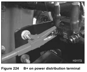

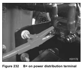
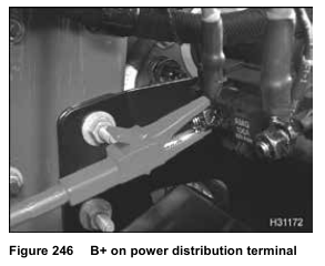
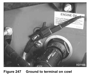
3. Apply B+ volts and ground to the IPR valve.
While cranking the engine, the engine could start.
• Set the parking brake
• Put transmission in neutral
• Block wheels.
CAUTION: Do not leave the IPR valve energized longer than 120 seconds — this can damage the IPR valve.
NOTE: If the engine starts, disconnect ground and B+ at the Actuator Breakout Harness.
4. Using the EST, monitor injection control pressure while cranking the engine for 20 seconds.
NOTE: If an EST is not available, use alternate method – Measuring Voltage on ICP Sensor using a Pressure Sensor Breakout Harness.
5. Record results on Diagnostic Form.
• If injection control pressure increases above 28 MPa (4061 psi) (4.45 V), the mechanical system is operating correctly for the engine to start. Either the ECM is not controlling the IPR or the IPR circuit has failed. Do not
continue with Low ICP System Tests.
Check DTCs found during Test 8 (KOEO Standard Test). Make sure problems were corrected.
• For problems in the electrical circuit, see “IPR (Injection Pressure Regulator)” in Section 7 (page 494).
• If 28 MPa (4061 psi) (4.45 V) can not be reached. Continue with the next test, 14.2 – Oil Reservoir Level.
14.2 – Oil Reservoir Level

1. Disconnect engine harness connector from EOT sensor installed in the rear of the front cover, left of the high- pressure oil pump assembly.
2. Slowly loosen the EOT sensor from the EOT port until oil flows out, indicating that the oil level is above the sensor. Oil will spill out, if the sensor is removed. Catch oil in a container. If oil does not flow out remove sensor.
• If the oil level was above the EOT sensor, tighten sensor and reconnect the harness.
Do test 14.3 – IPR and High-pressure Pump Operation.
• If oil level is low, place container under port to catch oil. Crank engine and check if oil flows out.
• If oil does not flow out while cranking, the lube oil pump may not be supplying oil to the reservoir. See “Low Oil Pressure” in Section 4 (page 128).
14.3 – IPR and High-pressure Pump Operation


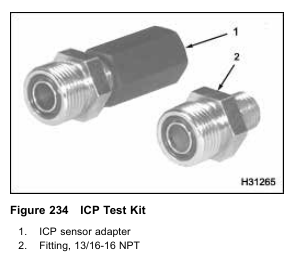
1. Make test hose assembly with the following components:
• ICP sensor adapter
• High-pressure hose (Part No. – 1842571C91 or equivalent)
• VT 365 ICP sensor (Part No. – 1845274C92 or equivalent)
NOTE: The mechanic is expected to keep the spare ICP sensor and high-pressure hose for future diagnostics. Expense the spare ICP sensor and high-pressure hose as essential tools and keep both with other diagnostic tools. Warranty will not cover the cost of the spare ICP sensor and high-pressure hose.

2. Disconnect high-pressure oil hose from high-pressure pump fitting.
NOTE: Oil will spill from hose. Position the high-pressure oil hose so oil will not spill.
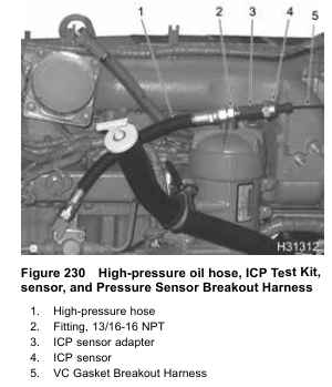
3. Install test hose assembly to high-pressure pump.
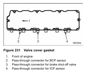
4. Disconnect engine wiring harness from valve cover gasket (ICP connector).
5. Connect VC Gasket Breakout Harness between high-pressure hose assembly and engine wiring
harness only.
NOTE: If connected to the valve cover, gasket connector – readings will be wrong, because the harness will be connected to the ICP sensor under the valve cover.
6. Connect Actuator Breakout Harness to IPR. Do not connect engine harness.
CAUTION: If the engine harness is connected to the actuator breakout harness, the ignition switch fuse will blow or cause damage to wiring harness.

7. Apply B+ volts and ground to the IPR valve.
8. Using the EST or DMM, monitor injection control pressure while cranking engine for 20 seconds.
Record results on Diagnostic Form.
• If injection control pressure increases above 28 MPa (4061 psi) (4.45 V), the high-pressure pump and IPR are operating correctly for the engine to start. Remove test hose assembly from high-pressure pump. Do test 14.4 – Under Valve Cover Leak Test.
• If 28 MPa (4061 psi) (4.45 V) can not be reached, continue with test 14.5 – IPR Function.
14.4 – Under Valve Cover Leak Test
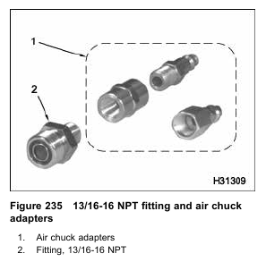
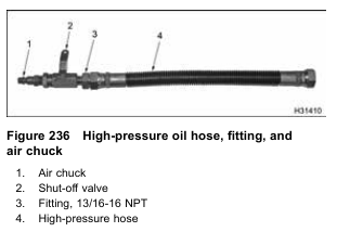
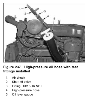
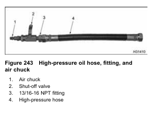
1.Install 13/16-16 NPT fitting, shut-off valve, and air chuck fitting to high-pressure oil hose connected to cylinder head.
2. Remove oil level gauge from oil fill tube.
3. Close shut-off valve.
4. Connect shop air supply line to test hose.
5. Apply 689 kPa (100 psi) of pressure. Slowly open the shut-off valve.
6. Listen for an air leak in the crankcase through the oil fill tube.
NOTE: Engines with engine brake option will have a small amount of air passing through the system.
Air will pass through brake shut-off valve into the brake oil gallery. The air will leak off through the actuator pistons and the relief valve at the end of the rail.
7. Record results on Diagnostic Form.
• If a leak is not heard, check previous test results.
• If a leak is heard, check components under the valve cover. Continue with step 8.
8. Close inline shut-off valve to stop air flow.
9. Remove the valve cover following procedures in the Engine Service Manual.
10. Open inline shut-off valve and listen for leaks.
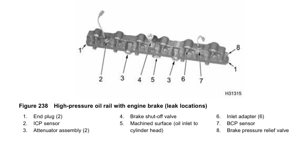
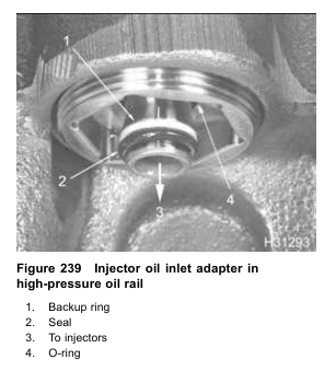
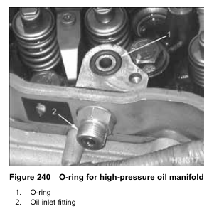
Check the following components:
• Injector oil inlet adapter O-rings (Figure 239)
• Injector oil inlet adapter (Figure 239)
• ICP sensor (Figure 238)
• O-ring for high-pressure oil rail (Figure 240)
• End plugs in high-pressure oil rail (Figure 238)
• Loose brake shut-off valve (optional) (Figure 238)
11. Replace or repair components, if necessary.
12. Install the valve cover following the procedures in the Engine Service Manual.
NOTE: Make sure all under valve cover wiring is routed correctly. Follow procedures in the Engine Service Manual.
• If engine is equipped with Diamond Logic® Engine Brake, and the high-pressure oil manifold has been removed, adjust the engine brake lash. Follow the procedure in Section 6 – Performance Diagnostics, Brake Lash.
14.5 – IPR Function


2. Install 13/16-16 NPT fitting, shut-off valve, and air chuck fitting to test hose.
3. Remove oil level gauge from oil fill tube.
4. Close the shut-off valve.
5. Connect shop air supply line to test hose.
6. Apply 689 kPa (100 psi) of pressure. Slowly open the shut-off valve.
7. Listen for an air leak in the crankcase through the oil fill tube.
• A leak should be heard through the IPR valve when the IPR valve is not energized.

8.Connect Actuator Breakout Harness to IPR. Do not connect engine harness.
CAUTION: If the engine harness is connected to the actuator breakout harness, the ignition switch fuse will blow or cause damage to wiring harness.
CAUTION: Do not leave the IPR valve energized longer than 120 seconds — this can damage the IPR valve.
9. Apply B+ volts and ground to the IPR valve. Listen for air leak in crankcase.
10. Record results on Diagnostic Form.
• If the IPR valve is energized, the air leak should stop.
• If the air leak does not stop, replace the IPR valve following the procedures in the Engine Service Manual. Repeat test 14.3 – IPR and High-pressure Pump Operation.
• If the air leak stops the IPR is functioning. The high-pressure pump is suspect because injection control pressure does not increase. Continue with next step.
11. Remove the high-pressure pump following procedures in the Engine Service Manual
• If high-pressure pump gear is loose, tighten, and reinstall high-pressure pump. Retest injection control pressure.
If ICP pressure is still below specification, replace the high-pressure pump.
• If high-pressure pump gear is tight, but the high-pressure pump cam does not rotate, suspect damage in the high-pressure pump. Replace the high-pressure pump and test.
Note: To inspect high-pressure pump cam, the fuel pump must be removed.