Purpose
To determine if the Inlet Air Heater assembly is operating correctly
Tools
• EST with MasterDiagnostics® software
• EZ-Tech® interface cable
• Digital Multimeter (DMM)
• Amp Clamp
15.1 – Current Amperage Draw
Procedure
NOTE: Inspect for damaged, loose or corroded terminals. Repair if necessary.

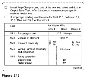
1. Install Amp Clamp around one of the two feed wires.
2. Turn the ignition switch to ON.

NOTE: When using the EST to do KOEO or KOER diagnostic tests, Standard Test is always selected
and run first. If the ignition switch is not cycled, the Standard Test does not have to be run again.
3. Select Diagnostics from the menu bar.
4. Select Key-On Engine-Off Tests from the drop down menu.
5. From the KOEO Diagnostics menu, select Glow Plug/Inlet Air Heater, then select Run to start the test.
6. Use the DMM and Amp Clamp to measure amperage. Record results on Diagnostic Form.
7. Repeat the above procedure for other feed wire circuit. Record results on Diagnostic Form.
• If amperage draw for both circuits meets specifications, do not continue with test. The Inlet Air Heater system is working correctly.
• If both circuits are not operational, confirm that the ECM is programmed and enabled for the Inlet Air Heater.
• When a failed circuit has been identified, check that circuit only.
• If amperage draw does not meet specification, continue with test 15.2 – Voltage at Element.
15.2 – Voltage at Element Terminal

1. Connect DMM positive lead to the element terminal that is out of specification.

2. Connect DMM negative lead to the ground terminal.
3. Turn the ignition switch to ON.

4. Select Diagnostics from the menu bar.
5. Select Key-On Engine-Off Tests from the drop down menu.
NOTE: When using the EST to do KOEO or KOER diagnostic tests, Standard Test is always selected and run first. If the ignition switch is not cycled, the Standard Test does not have to be run again.
6. From the KOEO Diagnostics menu, select Glow Plug/Inlet Air Heater, then select Run to start the test.
7. Use the DMM to measure voltage.
8. Record results on Diagnostic Form.
• If voltage is B+, do 15.3 Element Terminal Continuity.
• If voltage is not B+, do 15.4 – Wiring Harness Continuity and Resistance.
15.3 – Element Terminal Continuity
When the voltage at element is B+, check the continuity of the element terminal to ground.
1. Turn the ignition switch to OFF.
2. Use DMM to check resistance.

3. Connect DMM positive lead to the terminal that is not to specification. element

4. Connect DMM negative lead to the ground terminal.
5. Record results on Diagnostic Form.
• If the element does not have continuity to ground, replace the element.
• If the element has continuity, verify the previous Inlet Air Heater test.
15.4 – Wiring Harness Continuity and Resistance
When the voltage at element is not B+, measure the resistance (continuity) between the element and relay.
1. Turn the ignition switch to OFF.
2. Use the DMM to check wiring harness continuity and measure resistance.

3. Connect DMM negative lead to the element terminal that is not B+.
NOTE: Engines could be wired differently, having wiring harness connectors secured to different relay terminals. Trace wiring harness from element to the relay, to be sure that the correct relay terminal is being tested.
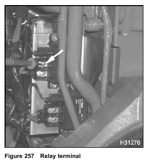
4. Contact DMM positive lead to relay terminal.
5. Record results on Diagnostic Form.
• If wiring resistance is > 5 Ω, repair or replace, if necessary.
• If wiring resistance is < 5 Ω, continue with test 15.5 – Relay Operation.
15.5 – Relay Operation

1. Connect DMM negative lead to the ground terminal, on the left side of crankcase or known, good ground in the cab.

NOTE: Engines could be wired differently, having wiring harness connectors secured to different relay
terminals. Trace wiring harness from battery to the relay, to be sure that the correct relay terminal is being tested.
2. Contact DMM positive lead to relay terminal of battery feed to relay.
3. Record results on Diagnostic Form.
• If DMM voltage at relay terminal is B+, continue with step 4 and measure relay output to element.
• If voltage of relay terminal is less than B+, repair or replace wire from starter to relay. Retest to verify repair.
4. Turn the ignition switch to ON.
5. Contact DMM positive lead to relay output terminal, relay to element.

6. Select Diagnostics from the menu bar.
7. Select Key-On Engine-Off Tests from the drop down menu.
NOTE: When using the EST to do KOEO or KOER diagnostic tests, Standard Test is always selected
and run first. If the ignition switch is not cycled, the Standard Test does not have to be run again.
8. From the KOEO Diagnostics menu, select Glow Plug/Inlet Air Heater, then select Run to start the test.
9. Record results on Diagnostic Form.
• If both relays are not operational, confirm that the ECM is programmed and enabled for the Inlet Air Heater.
• If both relays are not operational and the ECM programming is correct, do the following checks in “IAH System” – Section 7:
— Actuator Voltage Checks at ECM (page 449)
— Harness Resistance Checks – Relay to ECM (page 450)
— Harness Resistance Checks – Relay to 12–pin Connector (page 450)
• If voltage is not B+, do the following checks in “IAH System” – Section 7:
— Harness Resistance Checks – Relay to ECM (page 450)
— Harness Resistance Checks – Relay to 12–pin Connector (page 450)
If the control circuit wiring to the relay is correct, replace relay.
• If voltage is B+, verify previous test results. Check wiring from the relay to element.
The wiring may have continuity and low resistance. However, a poor crimp, loose connector, or corrosion could prevent ability to handle circuit load.
Possible Causes
• Failed wiring harness or connection
• Poor ground connection
• Failed relay
• Failed element
• Failed ECM
• ECM not programmed (inlet air heater)