Monitor the following parameters during one test drive:
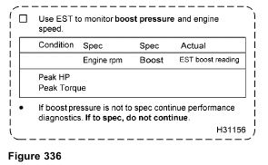
• Boost Pressure using EST
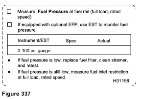
• Fuel Pressure using EST (optional, or mechanical gauge)
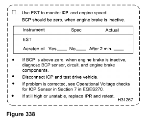
• ICP and BCP using EST
Monitoring Engine Parameters using EST and Fuel Pressure Gauge
Purpose
To verify engine performance at full load and rated speeds by means of maximum boost, minimum fuel pressure, and minimum injection control pressure
Tools
• EST with MasterDiagnostics® software
• EZ-Tech® interface cable
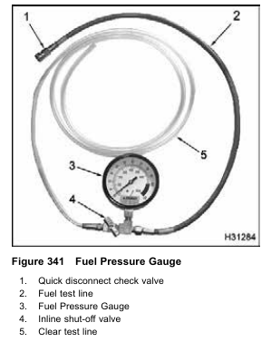
• Fuel Pressure Gauge
• Fuel Pressure Test Adapter
• Fuel/Oil Pressure Test Adapter
NOTE: If an EST is not available, use the Fuel Pressure Gauge setup in this procedure with the
alternative procedure for testing boost pressure (MAP), injection control pressure (ICP), and brake
control pressure (BCP) if equipped.
1. See “DT 466 Performance Specifications” – Appendix A (page 595) or DT 570 and HT 570 Performance Specifications” – Appendix B (page 619) for specifications and record on Diagnostic Form.
2. Does the engine have an optional Engine Fuel Pressure (EFP) sensor?
• If yes, the EST can record fuel pressure during the road test. Continue to step 5.
• If no, the fuel pressure must be measured with a mechanical gauge. Continue to step 3.
CAUTION: Be sure to place a rag or suitable container under the fuel pressure test valve when bleeding the
fuel rail. Dispose of fuel in a correct container clearly marked DIESEL FUEL according to local regulations.
NOTE: Engine fuel can be a threat to the environment.
Never dispose of engine fuel by putting it in the trash, pouring on the ground, in the sewers, in streams, or bodies of water.
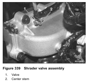
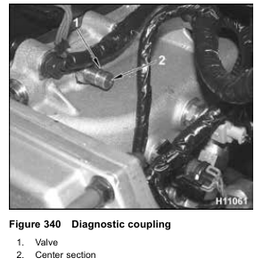
NOTE: Engines are equipped with a fuel pressure test valve in the form of either a Shrader valve or a diagnostic coupling.
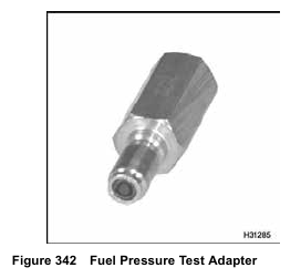
NOTE: If the engine is equipped with a Shrader valve, use the Fuel Pressure Test Adapter.
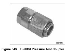
NOTE: If the engine is equipped with a diagnostic coupling, adapt the Fuel/Oil Pressure Test Coupler to
the Fuel Pressure Gauge.
3. Connect the Fuel Pressure Gauge and shut-off valve to the intake manifold fuel pressure test port.
NOTE: Breaking any fuel system joint will induce air into the fuel system. The air should pass in a short period of time.
4. Mount the Fuel Pressure Gauge where it can be seen from the drivers seat.
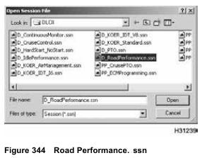
5. Open D_RoadPerformance.ssn to monitor engine operation.
6. Verify that the following are listed in the session and snapshot setup:
• Engine Speed (rpm)
• Engine Load (EL %)
• Boost Pres (MAP)
• Inject Ctrl Pres (ICP)
• Brake Ctrl Pres (BCP) – if equipped
• Fuel Delivery Pres (EFP) – if equipped
7. Drive vehicle and make sure engine operating temperature reaches 70 °C (158 °F) or higher.
8. Find a long, open stretch of road. When driving conditions are safe, select a suitable gear, press
accelerator pedal fully to the floor, and accelerate to rated speed at 100% load. Start the snapshot and, if a gauge is being used, monitor fuel pressure.
9. After the test is complete, park the vehicle. Replay the snapshot by selecting the following:
• Engine Speed (rpm)
• Engine Load (EL %)
• Boost Pres (MAP)
• Inject Ctrl Pres (ICP)
• Brake Ctrl Pres (BCP) – if equipped
• Fuel Delivery Pres (EFP) – if equipped
10. Record results on Diagnostic Form.
11. Review the results of boost pressure.
• If boost pressure is in specification, vehicle does not have a Performance Diagnostics problem at this time.
The issue and symptoms should be discussed with customer.
• If boost pressure is not to specification, continue to step 12.
12. Review the results of fuel pressure.
• If fuel pressure is in specification, continue with step 13.
• If fuel pressure is below specification, replace the filter, clean the strainer, and test again.
• If fuel pressure is still low after replacing fuel filter and cleaning the strainer, continue to “Fuel Inlet Restriction.”
13. Review the results of Inject Ctrl Pres (ICP).
• If the injection control pressure is in specification, do not continue with ICP system diagnostics.
• If the injection control pressure is not in specification, and is equipped with optional engine brake, continue to step 14.
• If the injection control pressure is not in specification, and is not equipped with optional engine brake, continue to step 15.
14. Review the results of Brake Ctrl Pres (BCP).
NOTE: BCP should be reading 0 kPa (0 psi). Values can fluctuate as high as 345 kPa (50 psi).
Electromagnetic Interference (EMI) or ground shift can cause an insignificant voltage shift that does not indicate a problem.
• If BCP is in specification, continue to step 15.
• If BCP is not zero when engine brake is inactive, diagnose the BCP sensor, circuit, and engine brake components.
NOTE: Engine fluids, oil, fuel, and coolant, can be a threat to the environment. Never dispose of engine fluids by putting them in the trash, pouring them on the ground, in the sewers, in streams or bodies of water.
Collect and dispose of engine fluids according to local regulations.
15. Turn off engine.
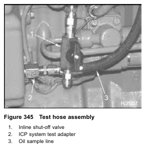
16. Use the ICP system test adapter and inline shut-off valve to make a test line assembly to take oil sample.
NOTE: The mechanic is expected to keep the test line for future diagnostics. Expense the test line as an essential tool and keep it with other diagnostic tools. Warranty will not cover the cost of the test line.
17. Remove EOT sensor from EOT port. Oil will spill out. Quickly install test hose assembly.
18. Run engine at high idle for 2 minutes.
19. Return engine to low idle, take oil sample, and check for aerated oil.
• If oil is aerated, a large quantity of air bubbles mixed throughout the oil, or foam build up on top of the oil will be seen. Check for cracked oil pickup tube or a missing or faulty pickup tube gasket.
• If oil is not aerated, disconnect ICP sensor and check engine stability. If problem is corrected, see “ICP Operational Voltage Checks” in Section 7.
• If ICP is still high or unstable, replace IPR following procedures in Engine Service Manual and retest.
Fuel Inlet Restriction
NOTE: This test should only be done if fuel pressure was low during test drive.
Tools
• Gauge bar (0–30 in Hg vacuum gauge)
• Fuel/Oil Pressure Test Coupler
• Test fitting
Procedure
1. See “DT 466 Performance Specifications” – Appendix A (page 595) or “DT 570 and HT 570
Performance Specifications” – Appendix B (page 619) for restriction specifications and record on Diagnostic Form.
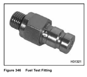
2. Remove cap from test fitting.
NOTE: If an O-ring plug is installed instead of a test fitting, remove O-ring plug and install Fuel Test Fitting.
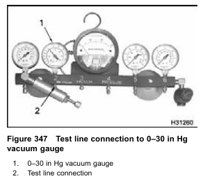
3. Connect test line to the Fuel/Oil Pressure Test Coupler and the 0–30 in Hg vacuum gauge.
4. Route test line from cab to engine.
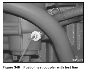
5. Connect Fuel/Oil Test Coupler to test fitting.
6. Drive vehicle and make sure engine operating temperature reaches 70 °C (158 °F) or higher.
7. Find a long, open stretch of road.
8. When driving conditions are safe, select a suitable gear, press accelerator pedal fully to the floor, and accelerate to rated speed at 100% load.
9. Memorize gauge reading for fuel inlet restriction.
After parking vehicle, record reading on Diagnostic Form; do not record reading while driving.
• If inlet restriction exceeds specification, find the restriction on the suction side of the fuel system and correct.
• If inlet restriction is to specification, but fuel pressure is below specification, test Operation of Fuel Pump in Test 6 of this section.
• If fuel pump is operating correctly, replace fuel regulator valve.
• If inlet restriction and fuel pressure are to specification, continue with performance diagnostics.
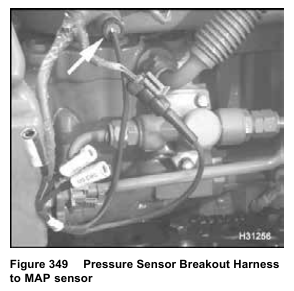
Monitoring Boost Pressure using Pressure
Sensor Breakout Harness
NOTE: Do this test only if an EST is not available. This is an alternate method.
Tools
• Pressure Sensor Breakout Harness
• DMM
1. See “DT 466 Performance Specifications” – Appendix A (page 595) ,“DT 570 and HT 570 Performance Specifications” – Appendix B (page 619) or Section 7 “Operational Voltages Checks” – for specifications and record on Diagnostic Form.
2. Connect Pressure Sensor Breakout Harness to MAP sensor and engine harness.
3. Use DMM to measure MAP at rated speed and full load.
• Connect POS to green (signal circuit) and NEG to black (ground circuit).
4. Route DMM and leads into cab.
5. Monitor DMM voltage signal for MAP.
6. Drive vehicle and make sure engine operating temperature reaches 70 °C (158 °F) or higher.
7. Find a long, open stretch of road.
8. When driving conditions are safe, select a suitable gear, press accelerator pedal fully to the floor, and
accelerate to rated speed at 100% load.
9. Memorize DMM voltage reading for boost pressure. After parking vehicle, record reading for boost pressure on Diagnostic Form; do not record reading while driving.
• If boost pressure is to specification, do not continue with Performance Diagnostics.
• If boost pressure is not to specification, continue Performance Diagnostics.
Monitoring ICP using VC Gasket Breakout Harness
NOTE: Do this test only if an EST is not available. This is an alternate method.
Tools
• VC Gasket Breakout Harness
• DMM
• ICP System Test Adapter
• Oil sample line with inline shut-off valve
• Clear container (for oil sample)
• Socket or wrench (EOT sensor)
1. See “DT 466 Performance Specifications” – Appendix A (page 595) ,“DT 570 and HT 570 Performance Specifications” – Appendix B (page 619) or Section 7 “Operational Voltages Checks” – for specifications and record on Diagnostic Form.
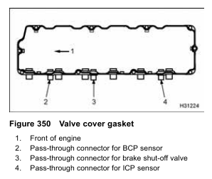
2. Disconnect engine harness connector from pass-through connector for the ICP sensor and complete steps 3 through 9.
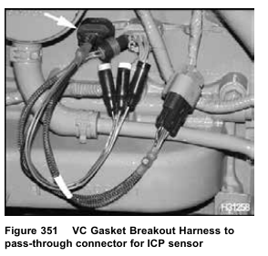
3. Connect VC Gasket Breakout Harness to the pass-through connector for the ICP sensor and engine harness.
4. Use DMM to measure ICP.
• Connect POS to green (signal circuit) and NEG to black (ground circuit).
5. Run DMM leads into cab.
6. Drive vehicle and make sure engine operating temperature reaches 70 °C (158 °F).
7. Find a long, open stretch of road.
8. When driving conditions are safe, select a suitable gear, press accelerator pedal fully to the floor, and accelerate to rated speed at 100% load.
9. Memorize DMM voltage for ICP. After parking vehicle, record reading on Diagnostic Form; do not record reading while driving.
• If ICP is to specification, do not continue with ICP system diagnostics.
• If ICP is not to specification, continue with step 10.
• If ICP is still unstable, replace IPR valve following procedures in the Engine Service Manual and retest
NOTE: Engine fluids, oil, fuel, and coolant, can be a threat to the environment. Never dispose of engine fluids by putting them in the trash, pouring them on the ground, in the sewers, in streams or bodies of water.
Collect and dispose of engine fluids according to local regulations.
10. Turn off engine.

11. Use the ICP system test adapter and inline shut-off valve to make a test line assembly to take oil sample.
NOTE: The mechanic is expected to keep the test line for future diagnostics. Expense the test line as an essential tool and keep it with other diagnostic tools. Warranty will not cover the cost of the test line.
12. Remove EOT sensor from EOT port. Oil will spill out. Quickly install test hose assembly.
13. Run engine at high idle for 2 minutes. Record ICP initially as high idle is set, then again after 2 minutes. Compare the two ICP readings. ICP that rises above the spec, at any point during the two minutes, indicates aeration.
14. Return engine to low idle, take oil sample, and check for aerated oil.
• If oil is aerated, a large quantity of air bubbles mixed throughout the oil, or foam build up on top of the oil will be seen. Correct condition.
• If oil is not aerated, disconnect ICP sensor and check engine stability. If problem is corrected, see “ICP Operational Voltage Checks” in Section 7.
• If ICP is still high or unstable, replace IPR following procedures in Engine Service Manual and retest.
Monitoring BCP using VC Gasket Breakout Harness
NOTE: Do this procedure, if an EST is not available.
This is an alternate method.
Tools
• VC Gasket Breakout Harness
• DMM
1. See “DT 466 Performance Specifications” – Appendix A (page 595) ,“DT 570 and HT 570 Performance Specifications” – Appendix B (page 619) or Section 7 “Operational Voltages Checks” – for specifications and record on Diagnostic Form.
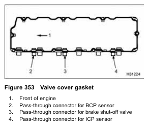
2. Disconnect engine harness connector from the pass-through connector for the BCP sensor and complete steps 3 through 9.
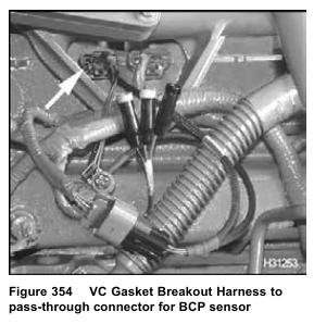
3. Connect VC Gasket Breakout Harness to the pass-through connector for the BCP sensor and engine harness.
4. Use DMM to measure BCP.
• Connect POS to green (signal circuit) and NEG to black (ground circuit).
5. Run DMM leads into cab.
6. Drive vehicle and make sure engine operating temperature reaches 70 °C (158 °F).
7. Find a long, open stretch of road.
8. When driving conditions are safe, select a suitable gear, press accelerator pedal fully to the floor, and accelerate to rated speed at 100% load.
9. Memorize DMM voltage for BCP. After parking vehicle, record reading on Diagnostic Form; do not record reading while driving.
• If BCP signal voltage is more than KOEO BCP signal voltage, when engine brake is inactive, diagnose BCP sensor, circuit, and engine brake components. The BCP voltage reading should be zero psi; however, BCP values may fluctuate as much as 345 kPa (50 psi). Electromagnetic Interference (EMI) or ground shift can cause an insignificant voltage shift that does not indicate a problem.
• If BCP signal voltage is equal to KOEO BCP signal voltage, there is no problem with the BCP sensor signal or the engine brake.