Rotate the engine to lock the crankshaft in place with the crankshaft locking pin, Part Number 2892115. Insert the pin in the hole in the crankshaft timing pin boss.
The colored band on the timing pin will be lined up with the surface of the timing pin boss of the block when seated correctly.
The pin is not correctly seated in the crankshaft notch if the colored band is either completely visible outside the block, or is not visible at all.
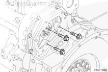
Place the camshaft guide onto the stud adapters as illustrated, without the wedge installed at this time. This will allow the guide to pass through the smaller bore rear camshaft gear.
Thread the mounting capscrews through the camshaft guide and into the stud adapters.
To prevent forward movement of the camshaft during installation of the expanding wedge, temporarily install the L-shaped clamp to the front of the gear housing as illustrated.
Rotate the camshaft 180 degrees. The plastic guide must be downward.
Fully insert the expanding wedge into the assembly and secure with an Allen head screw. This is to prevent the wedge from falling into the oil pan during the removal of the camshaft.
The plastic guide must be resting along the bottom of the camshaft bore.
Remove the camshaft by pulling slightly, with minor movement of the camshaft, to carefully work the camshaft through the camshaft bushings. As each camshaft journal passes through a bushing, the camshaft will drop slightly and the camshaft lobes will catch on the bushings. Movement of the camshaft will free the lobe from the bushing and allow the camshaft to be removed.


;)
;)
;)
;)
;)
;)
;)
;)
;)
;)
;)
;)
;)
;)
;)
;)
;)
;)
;)
;)