The injectors are arranged in the central area above the combustion chambers in the cylinder head.

As is also the case in existing nozzle holders in diesel engines with direct fuel injection, the injectors are held in the cylinder head with what are known as clamping shoes. The common rail injectors are therefore suited for installation into existing DI diesel engines without any major alterations being required.
The injectors therefore replace the nozzle holder combinations (nozzle and nozzle holder) used in conventional diesel injection units.
Task
The injector’s task is to set the injection start and injection quantity precisely.
The injector needle has a single guide so that the risk of needle friction can be prevented at design level.
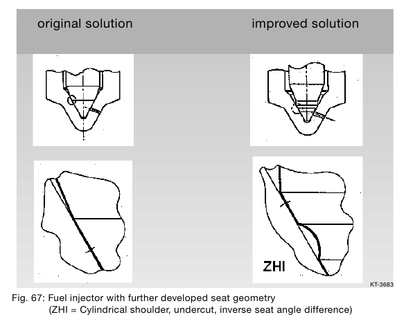
A highly developed lodgment geometry is also in service with the designation ZHI (cylindrical attachment, undercut, inverse lodgment angle difference). It is designed as what is known as a lodgment aperture nozzle. See following figure. The pressure compensation at the undercut creates symmetrical spraying. In addition, this lodgment geometry does not allow for any tendencies for increased quantities (quantity drift) as a result of wear to the unit.
Structure
The injector can be divided into a variety of function blocks:
• Hole nozzle with injector needle
• Hydraulic servo system
• Solenoid valve
• Connections and fuel channels

The high pressure connection (4) guides the fuel through a channel (10) to the nozzle and also through the supply
throttle (7) in the control chamber (5).
The control chamber is connected to the fuel return line (1) by the outlet throttle (8), which is opened by a solenoid valve. When the outlet throttle is closed, hydraulic force on the valve piston (9) exceeds that on the pressure stage of the injector needle (11). Consequently, the injector needle is pressed into its seat and seals the high pressure channel off from the engine compartment. Fuel cannot enter the combustion chamber, although it is constantly pressurized at the high pressure connection.
When the injector activation unit is actuated (2/2 solenoid valve), the outlet throttle is opened. This reduces the pressure in the control chamber, and therefore the hydraulic force on the valve piston.
As soon as the hydraulic force drops below that on the pressure stage of the injector needle, the injector needle opens, which allows the fuel to enter the combustion chamber through the spray apertures.
This indirect activation of the injector needle via a hydraulic force increasing system is used because the force required to open the injector needle using the solenoid valve cannot be produced directly. The control quantity required in addition to the fuel quantity injected enters the fuel return line via the control chamber throttle.
In addition to the pilot control volume, fuel is also lost (leakage quantity) at the nozzle needle and valve piston guides.
The control and leakage quantities can be up to 50 mm3 per stroke. They are guided back to the fuel tank via the fuel return line with a manifold, to which the overflow valve, high pressure pump and pressure control valve are connected.
Function
The function of the injector can be subdivided into four operating statuses when the engine is running and the high pressure pump is delivering fuel:
• Injector closed (under high pressure)
• Injector opens (start of injection)
• Injector fully open
• Injector closes (end of injection)
These operating statuses are applied according to the distribution of force amongst the components of the injectors. If the engine is not running and there is an absence of pressure in the rail, the nozzle spring closes the injector.
Injector closed (at rest)
When at rest, the 2/2-solenoid valve is not activated and is therefore closed (refer to Fig. cross-section of injector, a)
Because the outlet throttle is closed, the armature ball is pressed into the lodgment at the drain throttle by the valve spring. The rail high pressure accumulates in the valve control chamber. The same pressure is also exerted in the chamber volume of the nozzle. The forces applied by the pressure to the surfaces of the control piston and the force of the nozzle spring keeps the injector needle closed against the opening force attacking its pressure stage.
Injector opens (start of injection)
The injector is at rest. The 2/2-solenoid valve is activated by the starting current (I = 20 amps), which enables the 2/2 solenoid valve to be opened quickly (Fig. b). The force of the activated electromagnet exceeds that of the valve spring and the armature opens the final throttle. After a maximum of 450 ms, the increased starting current (I = 20 amps) is reduced to a lower retaining current of the electromagnet (I= 12 amps). This is possible because the air gap of the magnetic circuit is now smaller.
Opening the drain throttle allows fuel to flow out of the valve control chamber into the cavity above, and then to the fuel tank via the fuel return line. The inlet throttle prevents complete compensation from taking place and the pressure in the valve control chamber drops. As a consequence, the pressure in the valve control chamber is lower than the pressure in the chamber volume of the nozzle which still has the same level of pressure as the rail. The reduced pressure in the valve control chamber leads to less pressure being exerted on the control piston and to
the injector needle being opened. Injection commences.
The speed at which the injector needle opens is determined by the difference in throughput in the inlet and outlet throttle. After a stroke of approx. 200 mm, the control piston reaches its upper limit point and stays there, supported by a cushion of fuel. The cushion is created by the flow of fuel between the inlet and outlet throttle. The injector nozzle is now completely open and the fuel is injected into the combustion chamber at a pressure approaching that of the pressure in the rail.
Injector closes (end of injection)
If the 2/2 solenoid valve is no longer activated, then the armature is forced downwards by the force of the valve spring.
The ball then closes the outlet throttle. To prevent excessive wear from the contact between the ball and the valve seat, lodgment, the armature consists of two parts. Although the armature plate is guided downwards by a cam, it can also oscillate downwards by means of the reset spring, thereby preventing the armature and ball from being subject to any downward forces. As in the rail, closing the outlet throttle causes pressure to accumulate in the control compartment through the inlet of the inlet throttle. This increased pressure exerts greater force on the surface at the head end of the control piston. This force from the valve control chamber and the spring force exceed the force from the chamber volume, the injector needle closes. The speed at which the injector needle closes is determined by the throughput of the inlet throttle. Injection stops once the nozzle needle reaches its lower limit point.