This procedure requires that camshaft guide kit, Part Number 4919438, be used for proper installation and to prevent damage to the camshaft bushings in the cylinder block.
This procedure provides instructions on how to change the camshaft while the engine is still in the chassis and with the cylinder head installed. If the engine is removed from the chassis, removal of the flywheel housing should simplify the rear camshaft gear installation process.
Camshaft Guide Kit, Part Number 4919438
Item
Part Number
Description
Quantity
1
4919443
Socket Head Capscrew
2
2
4919442
Stud Adapter
2
3
4919451
Camshaft Guide
1
4
4919441
Expanding Wedge
1
5
4919444
Socket Head Capscrew
1
Not Shown
3018187
Hexagon Head Capscrew
1
Components of Camshaft Guide, Part Number 4919451, can be ordered separately, if needed.
Batteries can emit explosive gases. To reduce the possibility of personal injury, always ventilate the compartment before servicing the batteries. To reduce the possibility of arcing, remove the negative (-) battery cable first and attach the negative (-) battery cable last.
Disconnect the batteries. Refer to the OEM service manual
Rotate the engine to lock the crankshaft in place with the crankshaft locking pin, Part Number 2892115. Insert the pin in the hole in the crankshaft timing pin boss.
The colored band on the timing pin will be lined up with the surface of the timing pin boss of the block when seated correctly.
The pin is not correctly seated in the crankshaft notch if the colored band is either completely visible outside the block, or is not visible at all.
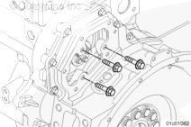
Place the camshaft guide onto the stud adapters as illustrated, without the wedge installed at this time. This will allow the guide to pass through the smaller bore rear camshaft gear.
Thread the mounting capscrews through the camshaft guide and into the stud adapters.
To prevent forward movement of the camshaft during installation of the expanding wedge, temporarily install the L-shaped clamp to the front of the gear housing as illustrated.
Rotate the camshaft 180 degrees. The plastic guide must be downward.
Fully insert the expanding wedge into the assembly and secure with an Allen head screw. This is to prevent the wedge from falling into the oil pan during the removal of the camshaft.
The plastic guide must be resting along the bottom of the camshaft bore.
Remove the camshaft by pulling slightly, with minor movement of the camshaft, to carefully work the camshaft through the camshaft bushings. As each camshaft journal passes through a bushing, the camshaft will drop slightly and the camshaft lobes will catch on the bushings. Movement of the camshaft will free the lobe from the bushing and allow the camshaft to be removed.
After the camshaft has been steam cleaned, do not touch the machined surfaces with bare hands. This will cause rust to form, which will damage the camshaft. Lubricate the camshaft with clean 15W-40 oil before handling.
Rotate the crankshaft clockwise until the ”Insert Pin” mark on the outside diameter of engine vibration damper is aligned with the slot, cut in the lower left of the front gear housing. Refer to Procedure 009-035 in Section 9.
Lock the crankshaft in place with the crankshaft locking pin, Part Number 2892115. Insert the pin in the hole in the crankshaft timing pin boss.
The colored band on the timing pin will be lined up with the surface of the timing pin boss of the block when seated correctly.
The pin is not correctly seated in the crank notch if the colored band is either completely visible outside the block, or is not visible at all.
Fully insert the expanding wedge into the assembly and secure with an Allen head screw. This is to prevent the wedge from falling into the oil pan during installation of the camshaft.
Do not force the camshaft into the camshaft bore, as damage to the camshaft bushing can result.
NOTE: The sequence to this installation is very important. Read these instructions thoroughly before proceeding.
Start at the front of the engine. The plastic guide must be resting along the bottom of the camshaft bore.
Install the camshaft by pushing slightly, with minor movement of the camshaft, to carefully work the camshaft through the camshaft bushings. As each camshaft journal passes through a bushing, the camshaft will drop slightly and the camshaft lobes will catch on the bushings. Movement of the camshaft will free the lobe from the bushing and allow the camshaft to be installed.
Stop installing the camshaft when the second camshaft journal is flush with the front gear housing.
Rotate the camshaft 180 degrees. The plastic guide should now be upward.
To prevent forward movement of the camshaft during removal of the expanding wedge, temporarily install the L-shaped clamp to the front of the gear housing as illustrated.
At the rear of the engine, remove the M6 Allen head capscrew that is securing the expanding wedge from the guide assembly.
There is a larger M8 thread, step machined into the M6 hole, for removing the wedge assembly. To remove the wedge assembly, thread a M8 capscrew into the wedge guide hole and pull out the wedge guide.
The camshaft guide will now insert into the same bore of the rear camshaft gear.
Do not force the camshaft into the camshaft bore, as damage to the camshaft bushing can result.
NOTE: The sequence to this installation is very important. Read these instructions thoroughly before proceeding.
At the front of the engine, finish installing the camshaft by pushing slightly, with minor movement of the camshaft, to carefully work the camshaft guide through the rear camshaft gear bore and the remaining camshaft bushings.
Remove the camshaft guide tool kit.
NOTE: Be sure the camshaft is completely installed and engaged completely with the rear camshaft gear before the thrust plate is tightened. The thrust plate must not be used to drive the camshaft into place. Doing so can result in damage to the thrust plate.
Insert the timing pin, Part Number 4919342, in the hole in the camshaft timing pin boss. Rotate the camshaft to find the slot in the camshaft and insert the timing pin.
The pin is not correctly seated in the camshaft notch if the green band is either completely visible outside the block, or is not visible at all.
Lock the camshaft in place with the camshaft locking pin, Part Number 4919342.
Batteries can emit explosive gases. To reduce the possibility of personal injury, always ventilate the compartment before servicing the batteries. To reduce the possibility of arcing, remove the negative (-) battery cable first and attach the negative (-) battery cable last.


 WARNING


 CAUTION


;)
;)
;)
;)
;)
;)
;)
;)
;)
;)
;)
;)
;)
;)
;)
;)
;)
;)
;)
;)
;)
;)
;)
;)
;)
;)
;)
;)
;)
;)
;)
;)
;)
;)
;)
;)
;)
;)
;)
;)
;)
;)
;)
;)
;)
;)
;)
;)
;)
;)
;)
;)
;)
;)
;)
;)
;)
;)
;)
;)
;)
;)